Scanning thermal microscope probe

A scanning thermal microscope and probe technology, which is applied in the field of scanning thermal microscope probes, can solve problems such as the inability to meet the temperature characterization of nanostructures, and achieve the effects of improving spatial resolution and thermal sensitivity, reducing costs, and good mechanical properties

Inactive Publication Date: 2007-03-28
TSINGHUA UNIV +1
View PDF0 Cites 8 Cited by
  • Summary
  • Abstract
  • Description
  • Claims
  • Application Information

AI Technical Summary

Problems solved by technology

However, the spatial resolution of the probes is generally limited to more than 50 nanometers, and even the latest reported experimen

Method used


Image

  • Scanning thermal microscope probe

Examples


Embodiment Construction

[0011] The present invention will be described in further detail below in conjunction with the accompanying drawings.

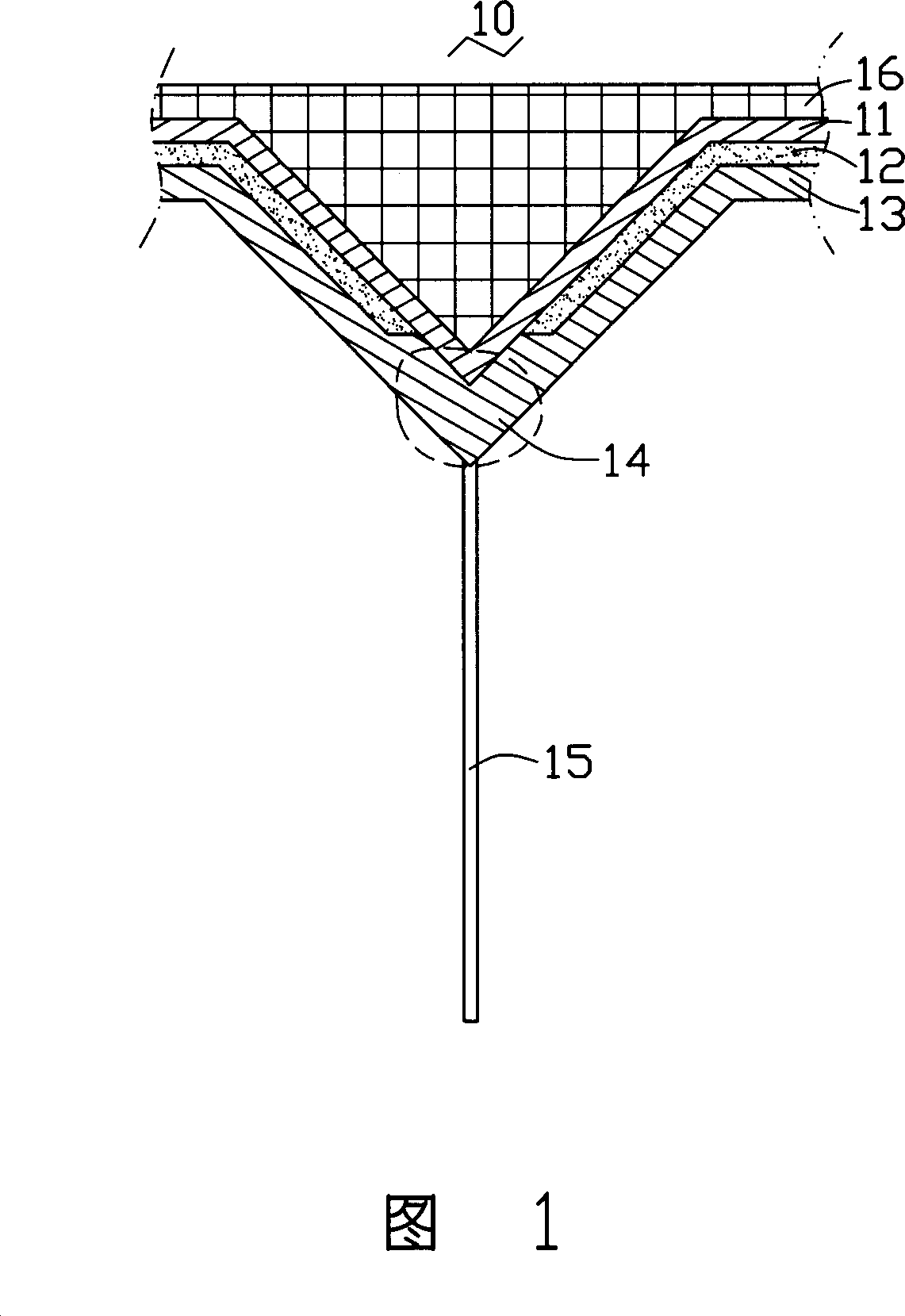
[0012] Please refer to Fig. 1 , the scanning thermal microscope probe 10 provided for the embodiment of the present invention includes: a cantilever 16; a first conductive layer 11 formed on the surface of the cantilever 16; an insulating layer 12 covering the cantilever 16 The surface of the first conductive layer 11 has a through hole; a second conductive layer 13 is covered on the surface of the insulating layer 12, and the first conductive layer 11 and the second conductive layer 13 are connected at the through hole to form a a thermocouple area 14; and a carbon nanotube 15 formed in the thermocouple area 14, one end is connected to the second conductive layer 13 at the thermocouple area 14, and the other end is a free end. Preferably, the carbon nanotubes 15 extend outwardly substantially perpendicular to the thermocouple region 14 .

[0013] The thermo...


PUM

PropertyMeasurementUnit
Resolutionaaaaaaaaaa

Abstract

The probe includes following parts: a cantalever; a first conductive layer formed on surface of the cantalever; having a through hole, an insulating layer of covering on surface of the first conductive layer; a second conductive layer of covering on surface of the insulating layer; the first conductive layer and the second conductive layer are connected at the through hole so as to form a thermocouple area; a Nano carbon tube formed on the thermocouple area. One end of the Nano carbon tube is connected to the second conductive layer at the thermocouple area, and the other end is as a free end. The Nano carbon tube is placed at tip of probe. Using microsize and axial heat-conducting property raises space resolution of scanning heatable stage microscope remarkably.

Description

【Technical field】 [0001] The invention relates to a scanning thermal microscope probe. 【Background technique】 [0002] In recent years, with the rapid development of nanotechnology, a series of measurement techniques for nanomaterials have emerged, the most notable of which is atomic force microscopy, which has extremely high resolution. Scanning thermal microscopy technology is developed on the basis of atomic force microscopy technology. It uses thermoelectric potential to measure the temperature and surface structure of nanomaterials by making miniature thermocouples on the atomic force microscope probe. At the same time, the excellent spatial resolution ability of the atomic force microscope is used to realize the precise measurement of the spatial distribution of temperature. [0003] When the scanning thermal microscope measures the surface structure of the material, the probe is first stabilized on the surface of the sample, and the junction is heated by direct curre...

Claims


Application Information

Patent Timeline
IPC IPC(8): G12B21/08G01N13/16B81B7/02G01K7/02G01N25/18G01Q60/00G01Q60/58G01Q70/00G01Q70/12
CPCG01K2211/00G01Q60/58G01Q10/00Y10S977/876Y10S977/867B82Y35/00G01Q70/12G01K7/028B82Y15/00
Inventor 姚湲刘长洪范守善
Owner TSINGHUA UNIV
Why Eureka
Try Eureka