Cascade optical parameter oscillating laser

An optical parametric oscillation and laser technology, applied in the field of lasers, can solve the problems of high cost and complex structure, and achieve the effects of low cost, high utilization efficiency and simple structure

Inactive Publication Date: 2007-03-28
TSINGHUA UNIV
View PDF0 Cites 9 Cited by
  • Summary
  • Abstract
  • Description
  • Claims
  • Application Information

AI Technical Summary

Problems solved by technology

[0003] In order to overcome the shortcomings of the aforementioned devices such as high cost and complex structure, and make full use of the light of two polarizations, the present invention uses the simple Faraday rotation mentioned in the document "Norman Hodgson, Horst weber, "Laser Resonators and Beam Propagatio

Method used


Image

  • Cascade optical parameter oscillating laser
  • Cascade optical parameter oscillating laser
  • Cascade optical parameter oscillating laser

Examples


Embodiment Construction

[0021] The present invention will be further described below in conjunction with the accompanying drawings and embodiments.

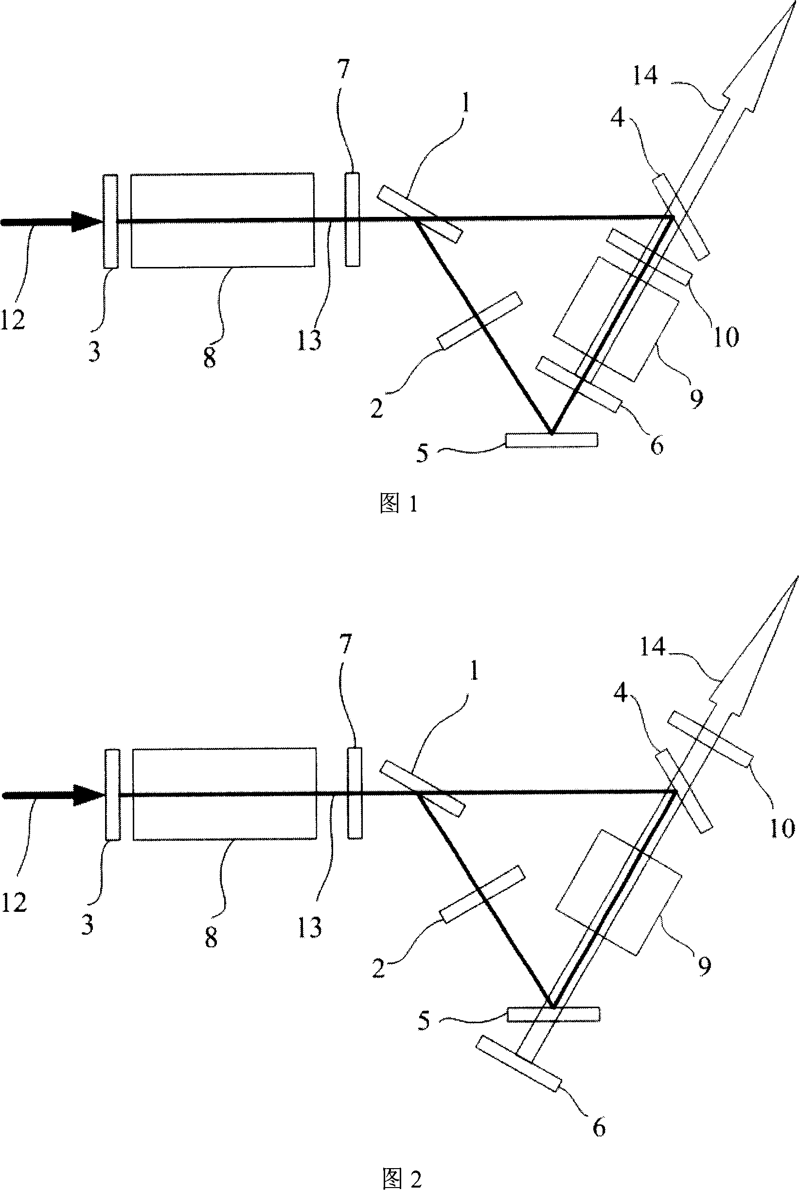
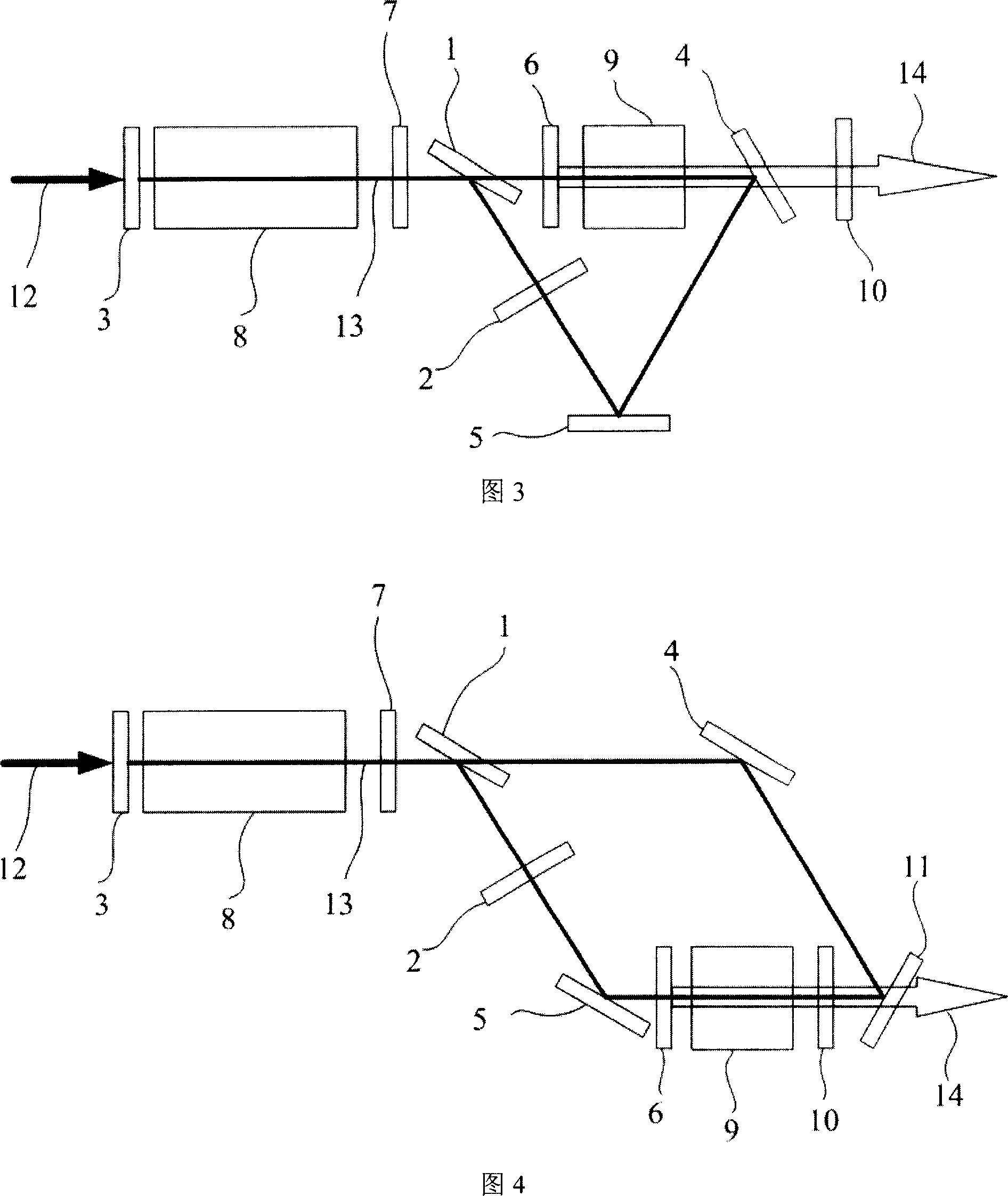
[0022] The first embodiment of the cascaded OPO of the present invention, as shown in FIG. 1 , includes a first-stage OPO, a second-stage OPO, and a polarized light recycling resonant cavity. Components in the above three parts share phenomenon. The first-stage OPO is degenerate or near-degenerate laser output, and the second-stage OPO is ordinary OPO output (degenerate or non-degenerate). The polarized light recycling resonant cavity is composed of the first resonant cavity and a ring cavity. The polarization beam splitting element 1 and the first cavity mirror 3 form the first resonant cavity; the polarization beam splitting element 1, the first mirror 4 and the second mirror 5 form a triangular ring cavity, and the three elements are located at three vertices of the triangular ring cavity . The polarization beam splitting element 1 is a common ele...


PUM


Abstract

In order to overcome disadvantages of high cost and complex structure existed in laser device in high power and long wavelength, the invention discloses new type structured cascading optical parametric oscillation laser device (OPOLD) in high average power. Using polarized beam splitter component couples a sect of resonant cavity to annular cavity. 90 degrees polarization rotator is placed in the annular cavity to constitute circulated resonant cavity of polarized light. Laser in cavity can realize polarization state circulated resonant of polarized light in two frequencies or near degeneracy. First stage OPOLD and second stage OPOLD are placed at suitable positions in optical path of the resonant cavity. First stage OPOLD outputs degenerate or near degenerate laser pumps second stage OPOLD to output laser in long wavelength. Features are: simple structure, low cost, and high utilization efficiency.

Description

technical field [0001] The invention belongs to the technical field of lasers, in particular to the cavity design of an Optical Parametric Oscillator (OPO for short). Background technique [0002] Mid-infrared long-wavelength lasers are a research hotspot. One of the methods to realize long-wavelength lasers is to pump the first-stage OPO with a laser of about 1 micron to generate a degenerate laser with a frequency of about 2 microns, and then pump the second-stage OPO with a degenerate laser of about 2 microns to generate Mid-infrared long-wavelength lasers (see J.A.C. Terry, K.J. McEwan, and M.J.P. Payne, "A tandem OPO route to the mid-IR," in Advanced Solid State Lasers, W.R. Bosenberg and M.M. Fejer, eds., Vol.19 of USA Trends in Optics and Photonics Series (OSA, 1998) pp. 236-239). In order to obtain a high average power mid-infrared output, a high average power 2-micron laser is required, so the nonlinear crystal of the first-stage OPO needs to have a high damage th...

Claims


Application Information

Patent Timeline
IPC IPC(8): H01S3/23H01S3/08H01S3/00
Inventor 巩马理何发红黄磊柳强陆丹闫平陈刚张海涛李晨
Owner TSINGHUA UNIV
Why Eureka
Try Eureka