Wheel power-generating device for retractable stator

A power generation device and stator technology, applied in the direction of electromechanical devices, auxiliary drive devices, electric vehicles, etc., can solve the problem of vehicles not being used, and achieve the effects of saving energy, reducing pollution, and improving fuel efficiency

Inactive Publication Date: 2007-03-28
陈冠卿
View PDF0 Cites 5 Cited by
  • Summary
  • Abstract
  • Description
  • Claims
  • Application Information

AI Technical Summary

Problems solved by technology

In addition, when the vehicle is driving on a downhill road, due to the attraction of the earth, the weight of the vehicle, the friction and inertia between the wheels and the ground, the vehicle w

Method used


Image

  • Wheel power-generating device for retractable stator
  • Wheel power-generating device for retractable stator

Examples


Embodiment Construction

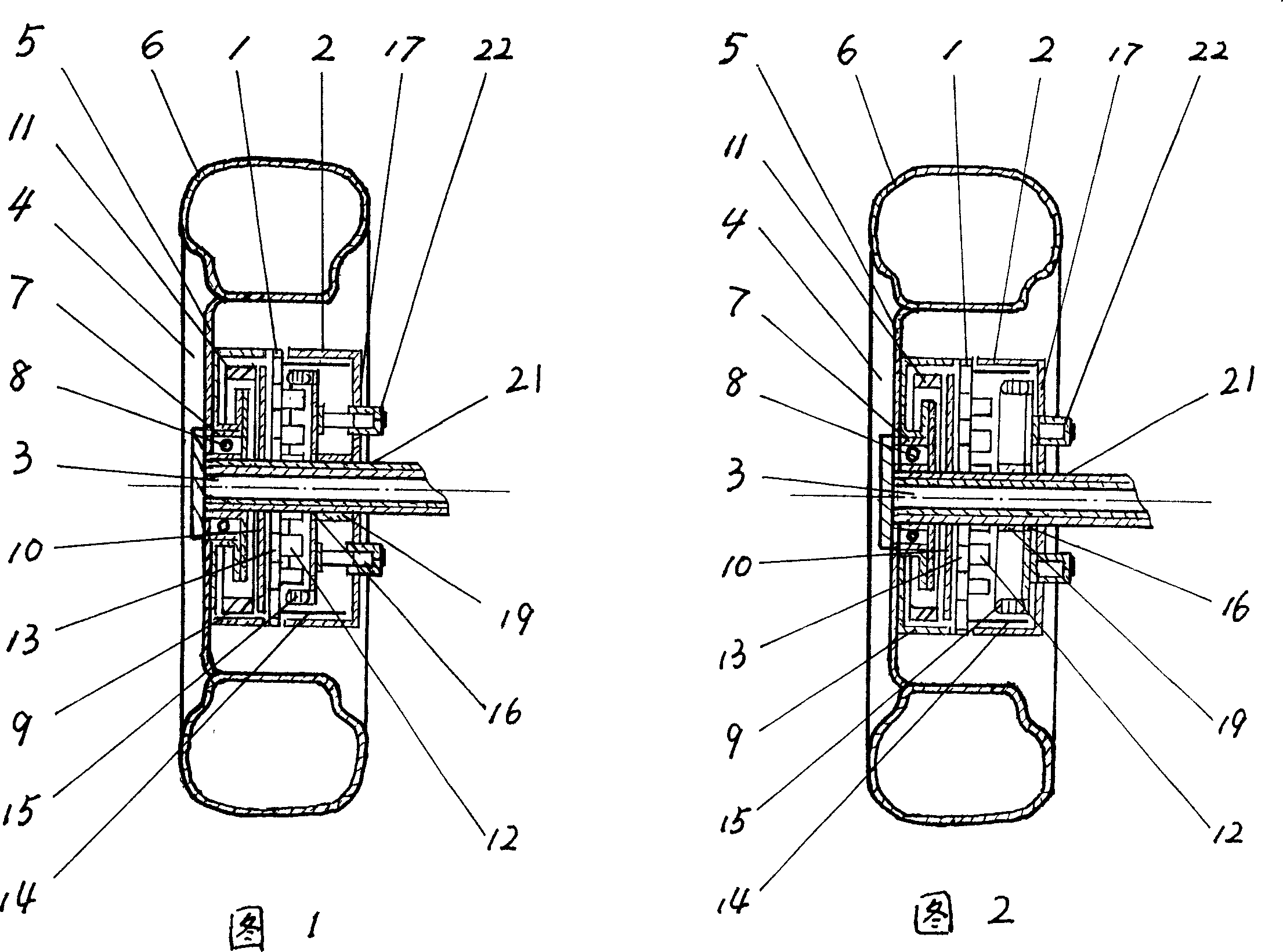
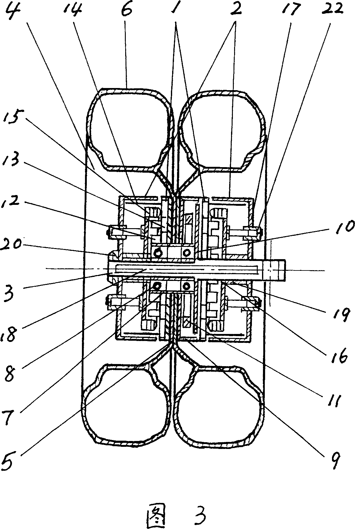
[0014] In the embodiment shown in Fig. 1 and Fig. 2, its structure and label are exactly the same, (1) is the wheel rotor, (2) is the axle end stator, (3) is the wheel axle. Wheel axle (3) is semi-axle when the rear axle of some automobiles. The wheel rotor (1) is composed of a wheel (4), a rotor (12), a fan (13) and a shroud (14). Wheel (4) is made of wheel rim assembly (5), tire (6), wheel hub (7), bearing (8) etc. (9) is a brake drum, (10) is a brake disc, and (11) is a braking device and an anti-lock braking device. The function of the rotor (12) is to generate a magnetic field, and is composed of a plurality of NdFeB rare earth permanent magnet materials and a carrier. There is an air inlet on one side of the fan (13), and the effect of the fan (13) is to prevent the present invention from being damaged due to excessive temperature during work, so that the air is forced to cool through the interior of the present invention at a high speed. Rotor (12), fan (13) and shro...


PUM


Abstract

The generating set includes wheel rotor, stub stator, wheel axis, stator slide way, sliding rack, and clutch of stator. The wheel rotor is composed of wheels, rotor, fan or centrifugal wheel, and shield. Stub stator includes stator, end plates, and rectifier. One side of clutch of stator is installed on end plate, and the other end if installed on stator. Based on different instances, such as ascent load, operation at low speed, uncrowned road, or downhill load, the makes stator separate fro or combine to rotor automatically through control system. Thus, using energy of inertia and downward subduction force, the invention can generate electric energy without affecting speed and load. Features are: repetitive cycling power generation, saving energy, and lowing pollution. The generating set is applicable to hybrid motor vehicles, military vehicles, new type motorcycles, and bicycles, even train.

Description

Technical field [0001] The invention relates to a wheel power generation device with a telescopic movable stator applicable to various vehicles, which belongs to electromechanical products. Background technique [0002] In modern society, motor vehicles are basically powered by various energy sources, such as automobiles, trains, and motorcycles, which are mostly powered by oil, natural gas, and electricity. In particular, automobiles mainly use gasoline, diesel or natural gas as fuel, and the heat energy of gasoline, diesel, and natural gas is converted into driving power through the engine to drive the wheels to rotate, so as to achieve the purpose of carrying people and goods in the car. In recent years, due to the development of social economy, all kinds of energy sources have been increasingly exhausted and their prices have risen, such as the recent rise in oil and coal prices, which has seriously harmed and restricted the development of human society and economy. In ...

Claims


Application Information

Patent Timeline
IPC IPC(8): H02K7/18B60L7/10B60K25/08
CPCY02T10/7241Y02T10/641Y02T10/64Y02T10/72
Inventor 陈冠卿陈洪涛陈洪波
Owner 陈冠卿
Why Eureka
Try Eureka