Infrared camera system

A camera and image technology, applied in the parts of TV systems, image communication, TV and other directions, can solve the problems of low output, limited resolution, and rising costs.

Inactive Publication Date: 2007-03-28
REDSHIFT SYST CORP
View PDF3 Cites 20 Cited by
  • Summary
  • Abstract
  • Description
  • Claims
  • Application Information

AI Technical Summary

Problems solved by technology

However, all of these "focal plane" technologies are expensive (for example, the lowest-priced video camera just broke the $10,000 barrier), making thermal imaging technology has yet to gain a dominant position in the commercial and consumer markets
Moreover, all existing products use inherently low-volume manufacturing techniques, driving up costs and limiting resolution (i.e., pixel count), which is a real problem for all uses except cost-insensitive other than use

Method used


Image

  • Infrared camera system
  • Infrared camera system
  • Infrared camera system

Examples


Embodiment Construction

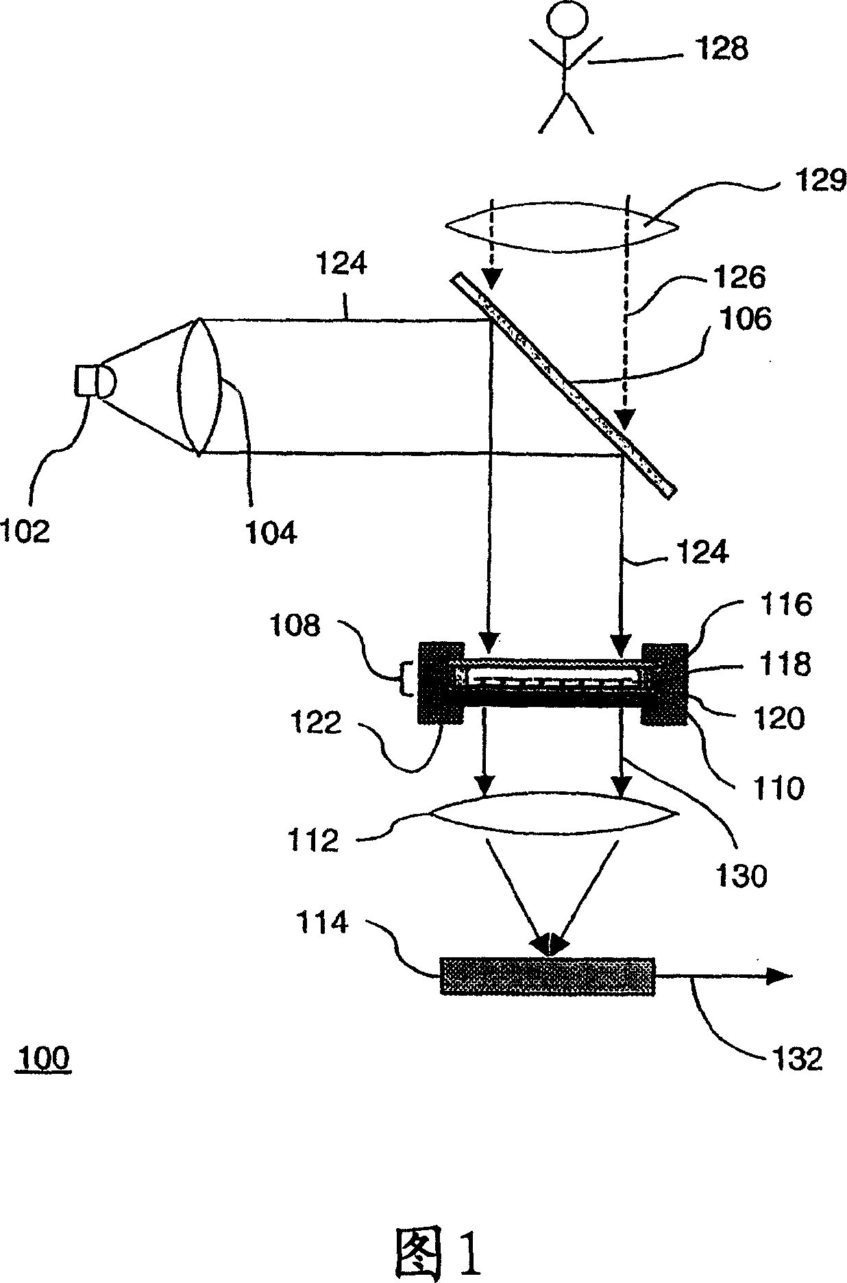
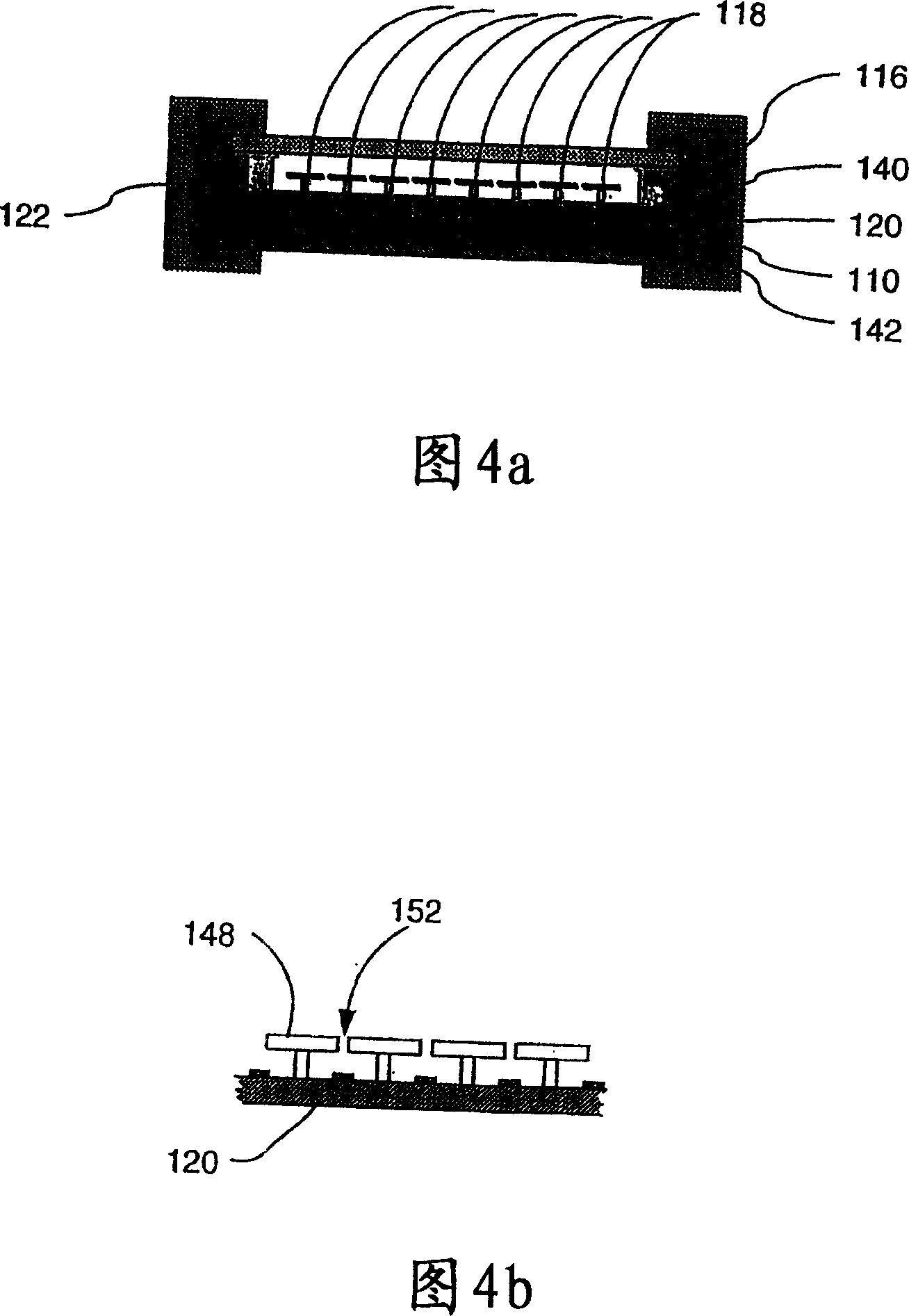
[0033] The described embodiment is an uncooled infrared (IR, infrared) camera system that uses a sensor that responds to infrared energy radiated by the scene to be imaged (although other wavelengths are also contemplated, typically 8 to 15 microns ( μm)—here, infrared is also referred to as infrared light or infrared radiation) thermally tunable filters. The filter element modulates a near-infrared (NIR) carrier signal (e.g., light having a wavelength of approximately 850 nanometers (nm)—also known as near-infrared optical signal, near-infrared light, probe, probe signal, or probe light) as infrared energy result of the change. The camera system uses a near-infrared detector (eg, a CMOS or CCD based imaging array, or a p-i-n photodiode array) to detect the modulated carrier signal.

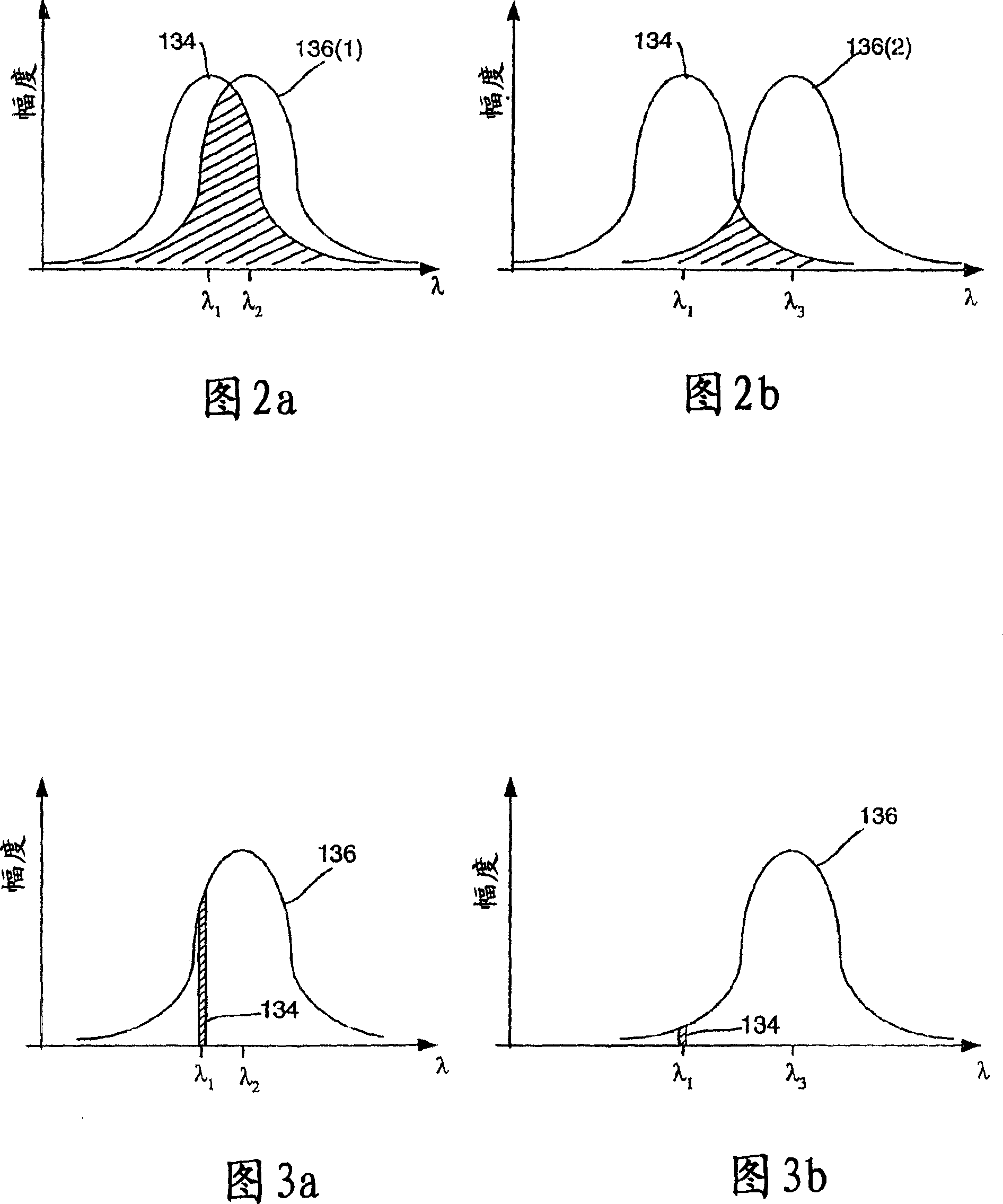
[0034] Infrared camera systems are based on thermal sensors using optical readout. The principle behind the thermal sensor described here is simple. A narrowband source produces an "optical ca...


PUM


Abstract

An IR camera system includes an array of thermally-tunable optical filter pixels, an NIR source and an NIR detector array. The IR camera system further includes IR optics for directing IR radiation from a scene to be imaged onto the array of thermallytunable optical filter pixels and NIR optics for directing NIR light from the NIR source, to the filter pixels and to the NIR detector arrays. The NIR source directs NIR light onto the array of thermally-tunable optical filter pixels. The NIR detector array receives NIR light modified by the array of thermally-tunable optical filter pixels and for produces an electrical signal corresponding to the NIR light the NIR detector array receives.

Description

technical field [0001] The present invention relates generally to thermal imagers. Background technique [0002] The market for infrared camera systems is large and rapidly growing, driven by military, security, medical, construction and automotive markets. Of particular interest are wavelengths between 7 and 15 microns, which have a high transmittance in the atmosphere, are less affected by sunlight, and are objects at normal ambient (room or body temperature) radiate at this wavelength. Several types of imaging systems are used to observe wavelengths other than visible light. These imaging systems range from arrays of narrow-bandgap semiconductor photodetectors, which typically require cryogenic cooling, to more recent arrays of uncooled microbolometers. However, all of these "focal plane" technologies are expensive (for example, the lowest-priced video camera has just broken the $10,000 barrier), making thermal imaging technology has yet to gain a dominant position in ...

Claims


Application Information

Patent Timeline
Patent Type & Authority Applications(China)
IPC IPC(8): H04N5/33
Inventor 马蒂亚斯·瓦格纳吴明(音译)尼古拉·涅姆钦科朱莉·库克理查德·戴维托罗伯特·姆拉诺劳伦斯·多玛什
Owner REDSHIFT SYST CORP
Why Eureka
Try Eureka