Light amount measuring apparatus and light amount measuring method

A light quantity measurement and light quantity technology, which is applied in the field of light quantity measurement equipment and light quantity measurement, and can solve the problems that absolute light quantity cannot be measured, quantitative evaluation of gene expression, etc.

Inactive Publication Date: 2007-04-04
YOKOGAWA ELECTRIC CORP
View PDF2 Cites 6 Cited by
  • Summary
  • Abstract
  • Description
  • Claims
  • Application Information

AI Technical Summary

Problems solved by technology

However, according to the prior art equipment, the absolute amount of light cannot be measured, and therefore, the amount of gene expression cannot be directly quantitatively evaluated

Method used


Image

  • Light amount measuring apparatus and light amount measuring method
  • Light amount measuring apparatus and light amount measuring method

Examples


Embodiment Construction

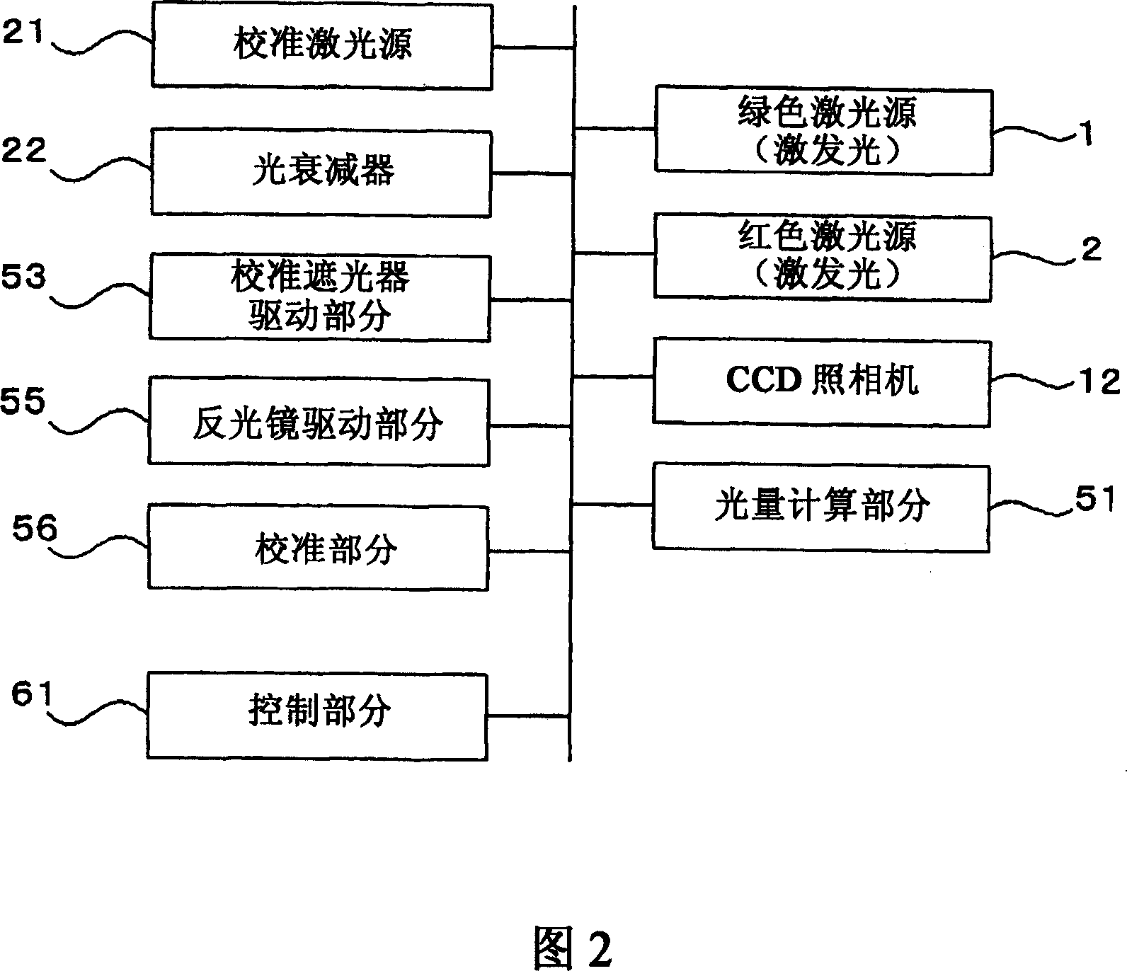
[0050] Next, the light quantity measuring device according to the present invention will be explained with reference to FIGS. 1 and 2.

[0051] Example.

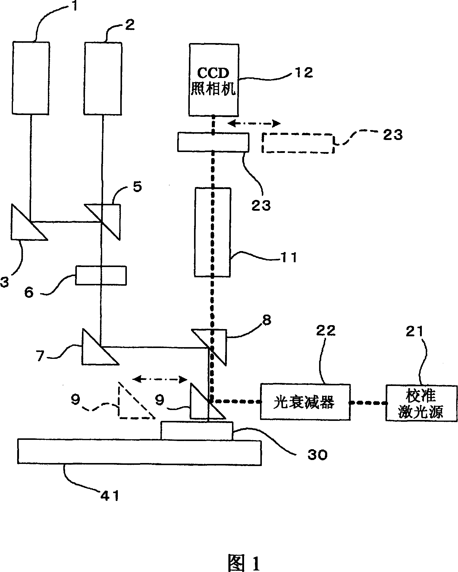
[0052] FIG. 1 is a diagram showing the configuration of an optical system of a light quantity measuring device according to the present embodiment. The present embodiment is a light quantity measuring device for measuring light produced at a DNA microarray by irradiating excitation light to the DNA microarray (DNA or RNA samples on the microarray (hereinafter, referred to as biochips)). Amount of fluorescent signal light.

[0053] As shown in FIG. 1 , the light quantity measuring device of this embodiment includes a green laser source 1 and a red laser source 2 for generating excitation light, a mirror 3 for bending the irradiation light from the green laser source 1, and respectively arranged Dichroic mirror 5 , microlens array 6 , reflective mirror 7 , dichroic mirror 8 and movable reflective mirror 9 on the optical path...


PUM


Abstract

A zero point adjustment is performed by generating no signal state of a CCD camera. A state in which stray light does not enter the CCD camera is ensured by a calibration shutter. An output signal of the CCD camera is transmitted to a light amount calculator, and a calibrating section executes a calibration for the light amount calculator by using an output signal value as a reference (zero point). Further, light outputted from a laser light source is attenuated by an optical attenuator and is made to be incident on the CCD camera. By switching an attenuating amount of the optical attenuator, correctly set light is made to be incident on the CCD camera. The output signal of the CCD camera is transmitted to the light amount calculator, and the calibrating section executes the calibration such that values of the respective output signals correctly correspond to respective light amounts.

Description

[0001] This application claims foreign priority based on Japanese Patent Application No. 2005-279506 filed on September 27, 2005, the entire contents of which are incorporated herein by reference. technical field [0002] The present invention relates to a light quantity measuring device and a light quantity measuring method for measuring the light quantity, and more particularly, the present invention relates to a light quantity measuring device and a light quantity measuring method capable of quantitatively evaluating the light quantity. Background technique [0003] As a method for identifying biopolymers such as DNA, a method using a microarray is known. For example, when DNA is recognized, a DNA probe having a known base sequence is immobilized to each site of a microarray, and DNA having a complementary base sequence is paired to each site by hybridization. By labeling paired DNA with a fluorescent label, the amount of pairing can be regarded as the amount of fluoresce...

Claims


Application Information

Patent Timeline
Patent Type & Authority Applications(China)
IPC IPC(8): G01J1/00G01N21/64
CPCG01N2021/6419G01J1/08G01N21/274G01N2021/6441G01N21/6428G01J1/4214G01N2021/6421G01N21/6452
Inventor 兰宗树田名纲健雄
Owner YOKOGAWA ELECTRIC CORP
Why Eureka
Try Eureka