Ultrasonic gas or cluter injector

An injector and gas technology, which is used in the reduction of greenhouse gases, climate sustainability, nuclear reactors, etc., can solve the problems of low gas particle orientation velocity, low orientation velocity, restricting the shape of the nozzle, etc., to promote the peaking of the plasma density distribution Effect

Active Publication Date: 2007-04-04
SOUTHWESTERN INST OF PHYSICS
View PDF1 Cites 13 Cited by
  • Summary
  • Abstract
  • Description
  • Claims
  • Application Information

AI Technical Summary

Problems solved by technology

There are some difficulties in increasing the plasma density with the conventional gas injection method. The existing problems are that the gas particle orientation speed is low, the divergence angle is large, and it can only be deposited in the radiation area at the edge of the plasma. The particle injection depth is only 3 to 4cm, and the feeding efficiency is low. About 15% to 30%
The piezoelectric crystal valve used in this feeding form inputs ga

Method used


Image

  • Ultrasonic gas or cluter injector

Examples


Embodiment Construction

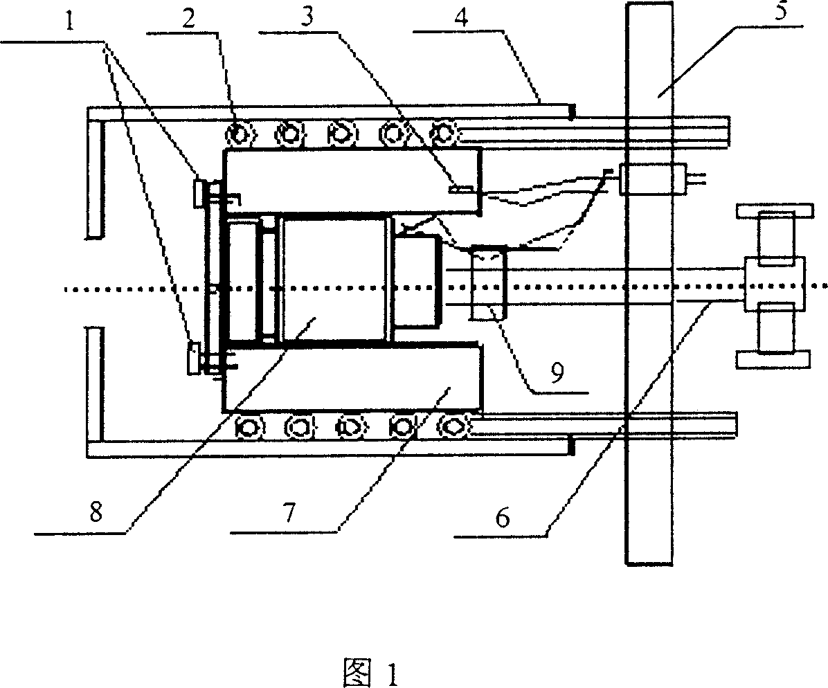
[0008] As shown in Figure 1, the ultrasonic gas or cluster injector includes a valve assembly, the valve assembly is fixed on the CF150 flange 5 connected with the vacuum chamber pipeline of the circulator, and the valve assembly is a gas jet valve 8 with a Laval nozzle, The valve can be purchased directly, the model is Series99, and other models with similar structure can also be selected or designed and manufactured by ourselves, but it is required to have the performance of vacuum and high pressure sealing at the temperature of liquid nitrogen. The gas jet valve 8 is connected to the high-pressure gas delivery pipe 6 through an A-lock connector 9, which can be vacuum-tight and can withstand an air pressure of 10 MPa. A liquid nitrogen cold trap 7 is arranged outside the gas jet valve 8, and the liquid nitrogen cold trap is a copper container filled with liquid nitrogen, which helps to improve heat transfer efficiency. The liquid nitrogen is injected into the copper container...


PUM


Abstract

A loading device for nuclear plant is composed by a valve part which is fixed to the flange on the pipe of the circulation vacuum chamber and is of a gas rejection valve with Laval nozzle, the gas rejection valve is linked to high pressure gas pipe and with liquid nitrogen cooling trap to outside then a magnetic screen. The injector prevents injected particles disperse and increase the injected amount and depth, so to increase plasma density and improve its inhibition character.

Description

technical field [0001] The invention relates to a feeding device of a nuclear fusion device. Background technique [0002] Conventional gas injection technology is widely used in the plasma feeding of existing nuclear fusion experimental devices. The technical measure is that high-pressure gas (air pressure is about 0.2 MPa) is continuously or pulsed into the vacuum chamber of nuclear fusion experimental devices through piezoelectric crystal valves. Used to create an initial plasma or increase the density of a plasma. There are some difficulties in increasing the plasma density with the conventional gas injection method. The existing problems are that the gas particle orientation speed is low, the divergence angle is large, and it can only be deposited in the radiation area at the edge of the plasma. The particle injection depth is only 3 to 4cm, and the feeding efficiency is low. About 15% to 30%. As the background plasma density increases, the feeding efficiency becomes ...

Claims


Application Information

Patent Timeline
IPC IPC(8): G21B1/15
CPCY02E30/16Y02E30/10
Inventor 姚良骅
Owner SOUTHWESTERN INST OF PHYSICS
Why Eureka
Try Eureka