Rail switching device for electric control switch

A turnout and track technology, applied in the field of track switch devices controlled by electric drivers, can solve problems such as small torque, difficult realization, and large current

Inactive Publication Date: 2007-04-11
史长春
View PDF0 Cites 9 Cited by
  • Summary
  • Abstract
  • Description
  • Claims
  • Application Information

AI Technical Summary

Problems solved by technology

[0003] The existing pneumatic turnout switch machine converts electric energy into air compressed gas, and uses the cylinder to push the connecting rod to perform track switching. The pneumatic turnout switch needs to convert electric

Method used


Image

  • Rail switching device for electric control switch
  • Rail switching device for electric control switch
  • Rail switching device for electric control switch

Examples


Embodiment 1

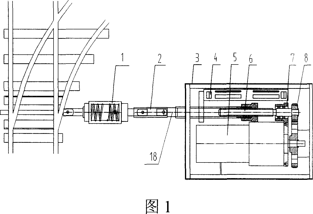
[0024] Embodiment 1: The track switch machine has an electric controller and a pusher, and the electric controller is connected with the track through the pusher.

[0025] The electric controller has a power machine and a push rod, and the power machine is connected with the push rod.

[0026] Described power machine has box body 3, and in box body 3, motor 5, travel switch 4, thread pair 6, gear pair 8 and frame 7 are arranged, and travel switch is positioned at one side in the box body, and motor is positioned at the other side in the box body. On the side, there is a threaded pair between the limit switch and the motor, the shaft of the threaded pair is connected to the frame, one end of the shaft of the threaded pair is connected to the push rod, the other end is connected to the gear pair, and the driving wheel of the gear pair is connected to the motor.

[0027] The pusher has a breakout buffer 1, and the breakout buffer has a cover with a spring in the cover, and a conn...

Embodiment 2

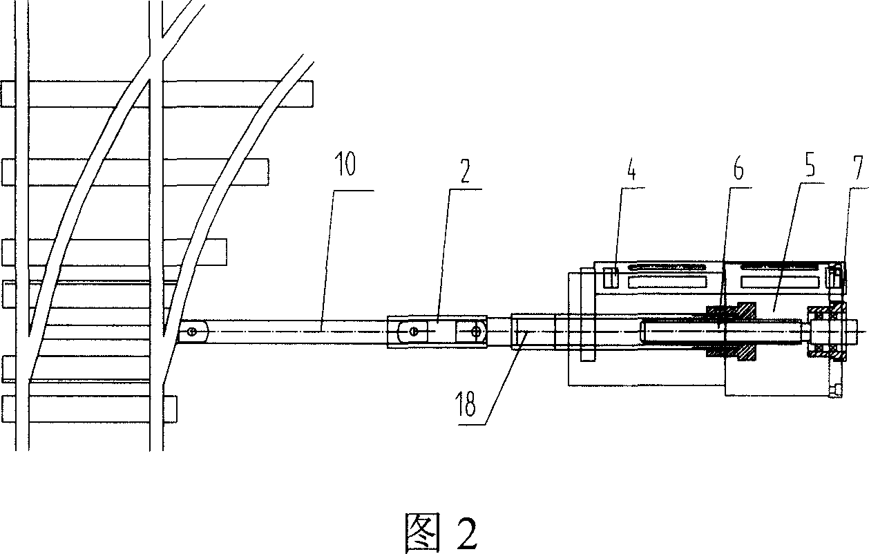
[0028] Embodiment 2: The power machine described is the vertical structure of the power machine in Embodiment 1, the pusher is the connecting rod 19, and the push rod is connected with the track through the connecting rod. Others are the same as in Example 1. slightly.

Embodiment 3

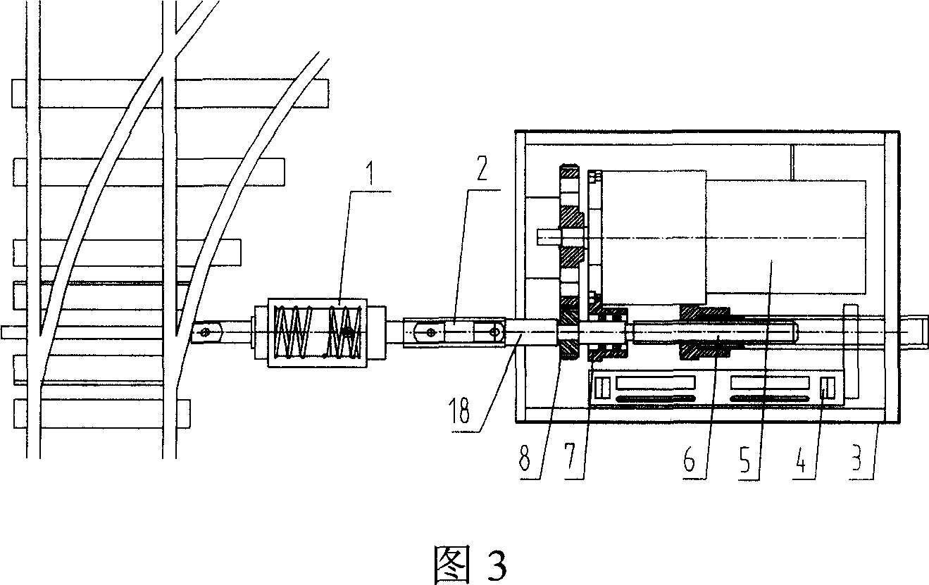
[0029] Embodiment 3: described power machine comprises electric motor 5, travel switch 4, push rod 18, thread pair 6, gear pair 8 and frame 7, and the shaft of thread pair 6 is connected on the frame 7, at one end of thread pair Sequence is connected with push rod 18 and gear pair 8, and the driving wheel of gear pair is connected with motor 5, and travel switch 4 is positioned on the motion locus of screw thread pair, and other is the same with embodiment 1, omits.


PUM


Abstract

The present invention relates to rail switching device, and is especially one kind of rail switching device for electrically controlled switch. The rail switching device includes an electric controller and a driver to connect the electric controller to the rail. The electric controller has a power machine and a push rod connected to the power machine. The switch controlling process includes the steps of changing voltage, converting the rotating force into linear force with the motor, changing drive moment mechanically and pushing or pulling the switch rail with the driver, and has great drive moment and small operating current. The rail switching device has also built-in lead screw, small DC permanent motor, inside micro reducer and contact-less stroke switch, and possesses reduced size, raised reliability and capacity of realizing automatic control.

Description

technical field [0001] The invention relates to a track switch machine, in particular to a track switch device controlled by an electric driver. Background technique [0002] At present, railways, mines, metallurgy, and power plants generally use rails to transport goods. When transferring the transported goods from one track to another, it is generally to move the switch machine, which changes the track and makes the truck change its driving. For the track route, the moving switch machine is generally controlled manually or automatically, and the movement of the switch rail is controlled to make the track switch. [0003] The existing pneumatic turnout switch machine converts electric energy into air compressed gas, and uses the cylinder to push the connecting rod to perform track switching. The pneumatic turnout switch needs to convert electric energy into air compressed gas, and the torque is small and the current is large. , In coal mine ro...

Claims


Application Information

Patent Timeline
IPC IPC(8): B61L5/06
Inventor 方岚吕清华蔡峰史长春
Owner 史长春
Why Eureka
Try Eureka