Novel three dimension fabric knitting machine

A technology of three-dimensional fabrics and knitting machines, applied in the field of knitting machines, which can solve problems such as increased resistance, long intermediate transmission chains, shuttle movement and poor positioning accuracy, and achieve reduced machining volume, low processing costs, and small mechanical friction Effect

Inactive Publication Date: 2007-04-11
冯威
View PDF5 Cites 7 Cited by
  • Summary
  • Abstract
  • Description
  • Claims
  • Application Information

AI Technical Summary

Problems solved by technology

Because the traditional three-dimensional fabric knitting machine always uses a mechanical "track" to guide the shuttle, the mechanical structure of the traditional three-dimensional fabric knitting machine is complicated, the manufacturing cost is high, and what is more serious is the positional relationship and motion relationship between the shuttles. Restricted by each other, it is difficult to meet the requirements of the current and emerging weaving methods for the movement of the shuttle, and it also restricts the expansion of the function of the knitting machine. However, it increases sharply, and at the same time, because the shuttles in the same row or column are all driven from the end of the row or column, the transmission chain in the middle is longer, which will inevitably cause the movement and positioning accuracy of the shuttles to be poor. The increase of the number will make this phenomenon more serious. Both of these two points will promote the "stuck" phenomenon in the movement of the shuttle and restrict the weaving size of the traditional three-dimensional fabric knitting machine.
Chinese patent 96109123.1 overcomes the "stuck" phenomenon of the traditional three-dimensional fabric knitting machine, and expands the size of the knitting machine from 30 rows to a maximum of 200 rows, but this technology also increases the difficulty and cost of mechanical processing, and does not fundamentally solve " The hidden danger of "stuck"

Method used


Image

  • Novel three dimension fabric knitting machine
  • Novel three dimension fabric knitting machine
  • Novel three dimension fabric knitting machine

Examples


Embodiment Construction

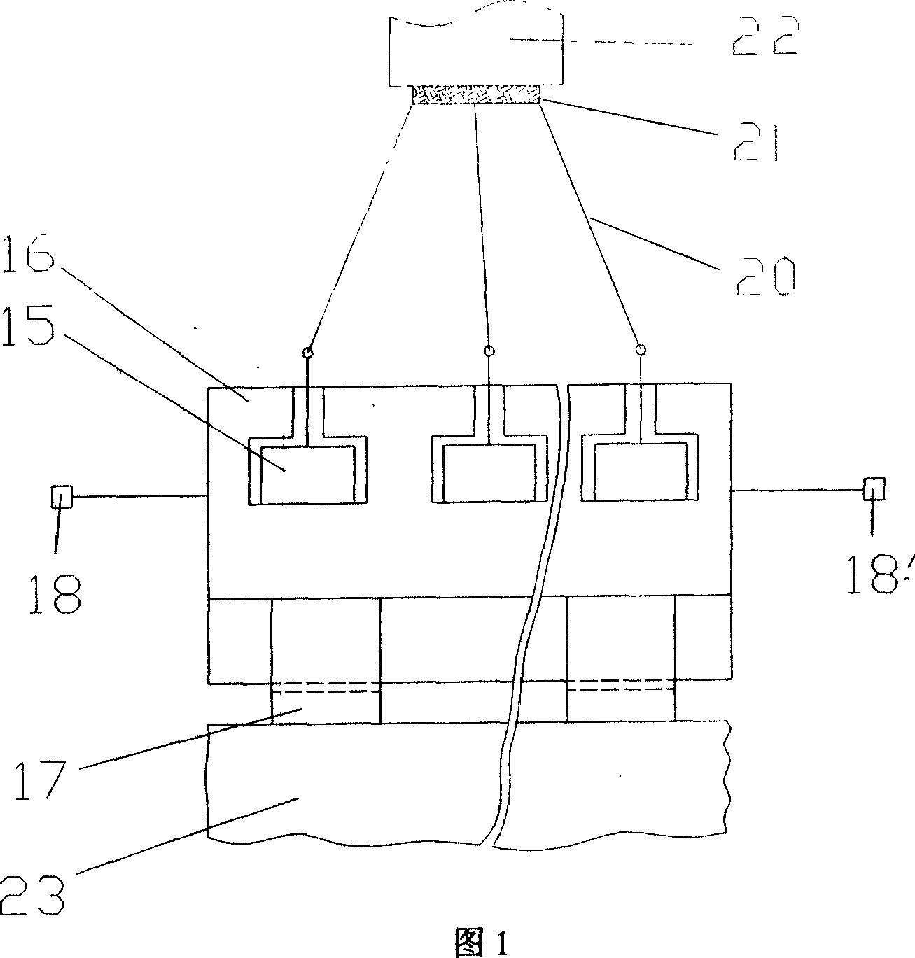
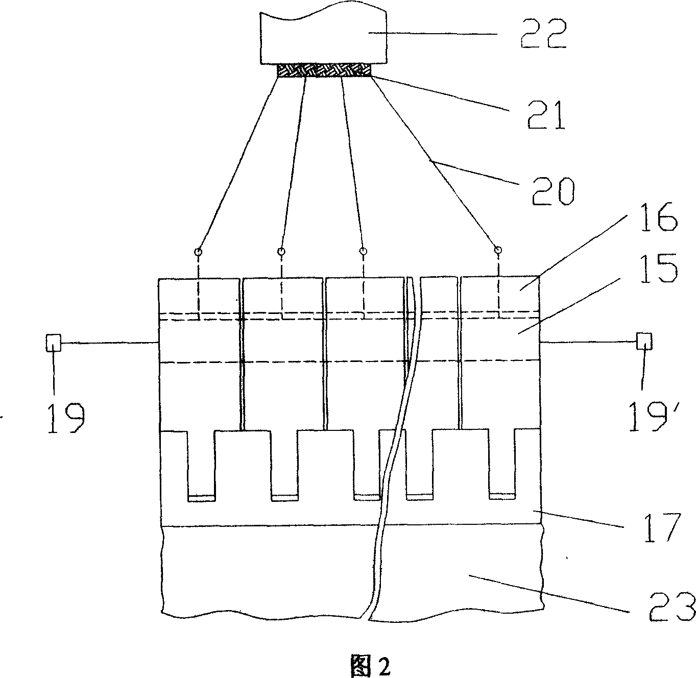
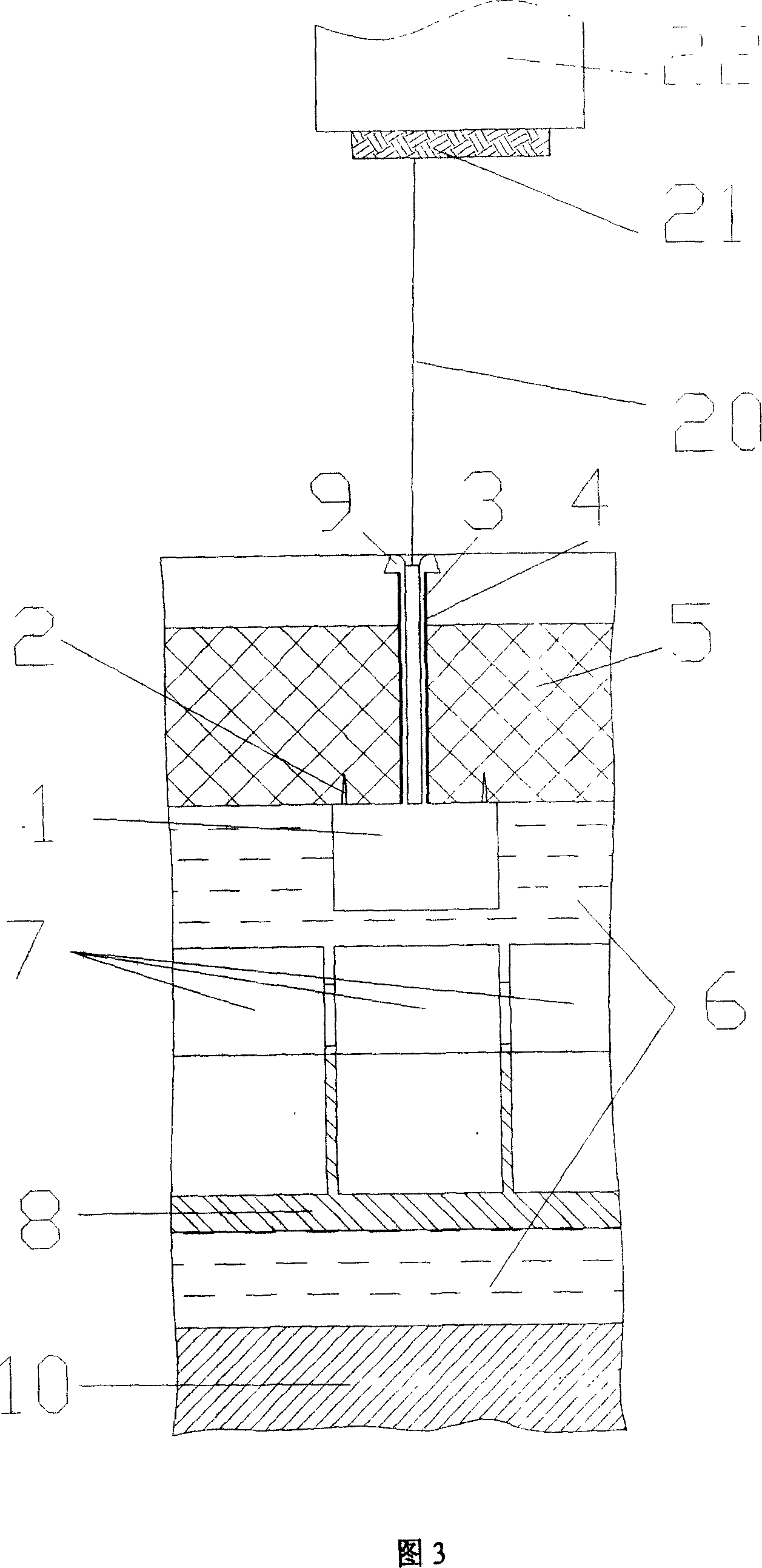
[0025]The knitting machine of the present invention keeps the structural form of the fabric forming device 22 in the traditional three-dimensional fabric knitting machine basically unchanged, and its key point is to redesign the chassis of the knitting machine (see Fig. 3). The solid-liquid two-phase chassis is composed of two different material layers, the upper and lower layers. The chassis function is completed through the specific material properties of the upper and lower material layers. Among these two layers, the upper layer 5 is called the solid phase layer, and the lower layer 6 is called the solid phase layer. liquid layer. Shuttle is made up of yarn storage device 1, yarn bobbin 3, heating wire 4, increases the fixed cone 2 and stop cap 9 that play auxiliary role simultaneously. Shuttle is driven by driving arm 8, and driving hand 7 realizes various knitting motions. There is a detachable docking interface between the yarn storage device 1 of the shuttle and the d...


PUM


Abstract

The vertical 3D fabric knitting machine includes one solid-liquid two phase under pan comprising one liquid phase layer and one solid phase layer floated on the liquid phase layer; one shuttle comprising yarn storing device, bobbin on the yarn storing device and electric heating wire outside the bobbin; one driving device comprising driving hand and driving arm; and one frame for the other parts to be set on. The solid phase layer is normally solid and may be converted into liquid state after being heated and returned to solid state after being cooled; the liquid phase layer is always in liquid phase; the bobbin and the electric heating wire penetrate the solid phase layer; the yarn storing device is located inside the liquid phase layer and connected to the driving hand via one separable interface; and the electric heating wire is connected to the power source. The said structure makes it possible for the shuttle to move in any locus in the under pan plane and is simple and low in cost.

Description

technical field [0001] The invention relates to a weaving machine for three-dimensional fabrics or three-dimensional weaving composite materials, in particular to a vertical weaving machine for three-dimensional fabrics. Background technique [0002] Three-dimensional fabric or three-dimensional braided composite material is a new type of composite material developed on the basis of two-dimensional braided composite materials in recent years. The physical and mechanical properties such as high speed and high temperature are obviously superior to traditional laminated composite materials, so it is a new material for key parts in aerospace, weaponry, transportation, petrochemical, sports equipment, medical equipment and many other fields. [0003] The three-dimensional fabric weaving machine is the processing equipment for this three-dimensional weaving composite material. Traditional three-dimensional fabric knitting machines can basically be divided into two categories: ver...

Claims


Application Information

Patent Timeline
Patent Type & Authority Applications(China)
IPC IPC(8): D04C3/00
Inventor 冯威
Owner 冯威
Why Eureka
Try Eureka