Coal burning hot-blast stove

A hot blast stove and coal-fired technology, which is applied in heating devices, air heaters, fluid heaters, etc., can solve the problems of poor heat transfer effect, low utilization rate of heat energy of hot blast stove, and difficult to remove dust accumulation in heat exchange tubes, etc. Achieve the effect of high utilization rate of heat energy and convenient removal of smoke and dust accumulation

Inactive Publication Date: 2010-05-12
康秉荣
View PDF0 Cites 0 Cited by
  • Summary
  • Abstract
  • Description
  • Claims
  • Application Information

AI Technical Summary

Problems solved by technology

The disadvantages of this structure of coal-fired hot blast stove are: it is difficult to remove the soot and ash in the heat exchange tube; the heat transfer effect is poor, and the utilization rate of heat energy of the hot blast stove is low

Method used


Image

  • Coal burning hot-blast stove
  • Coal burning hot-blast stove
  • Coal burning hot-blast stove

Examples


Embodiment Construction

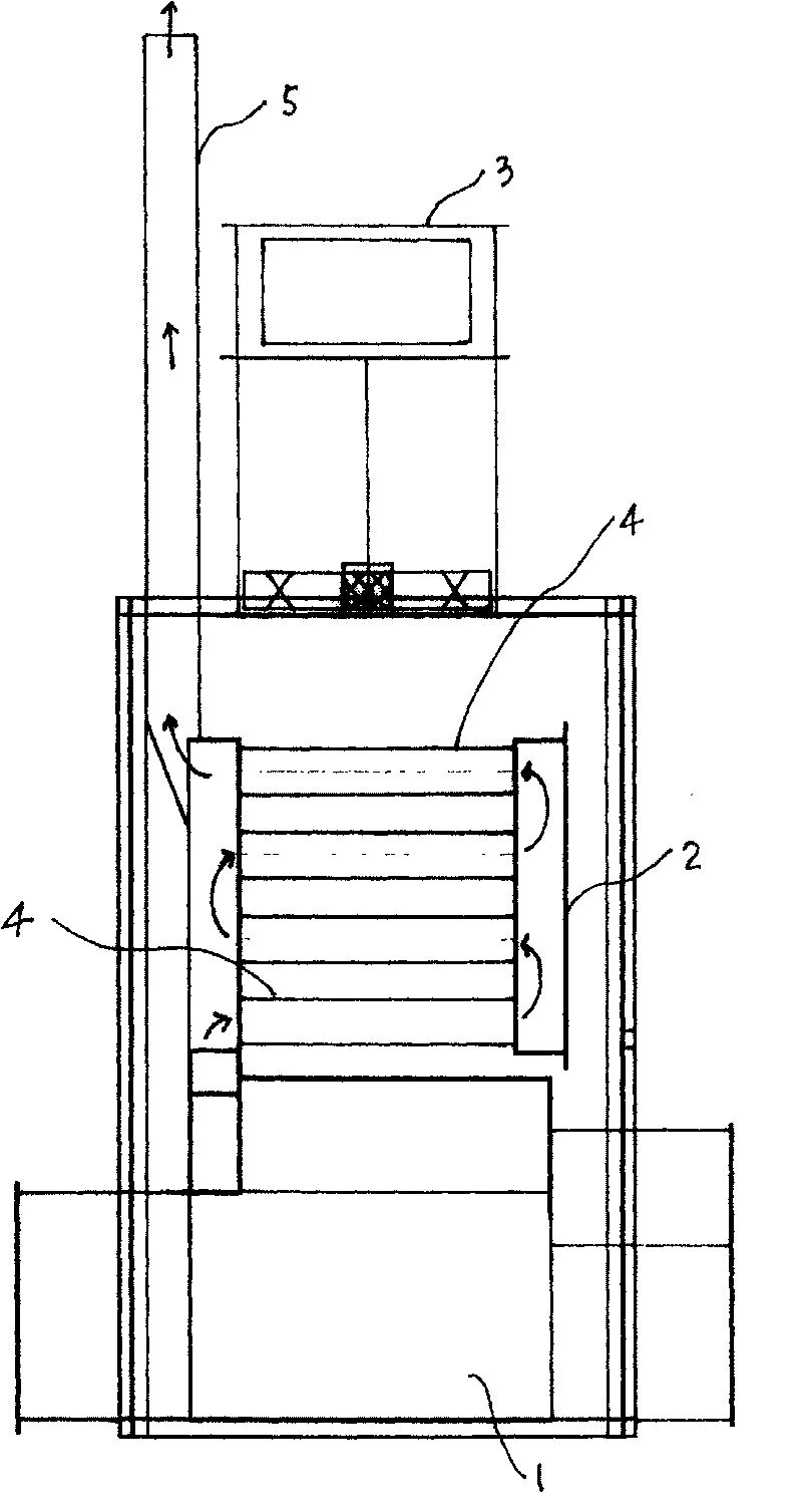
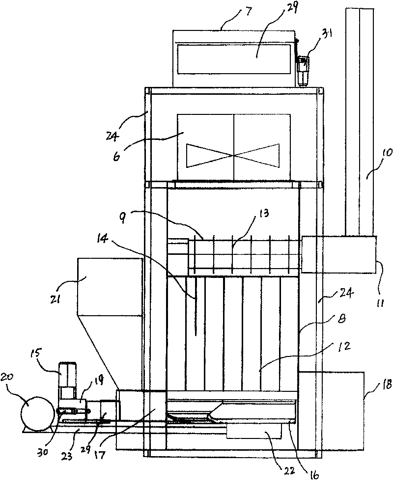
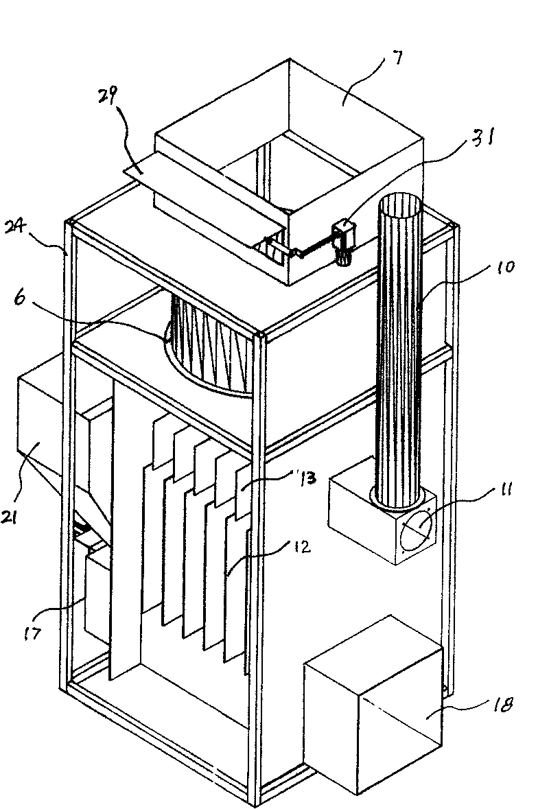
[0018] See Figure 2-6 In the embodiment shown, the coal-fired hot air stove is used for the primary roasting of tobacco leaves.

[0019] An air inlet 7 and a blower 6 are arranged on the upper part of the hot blast stove. The combustion transducer 8 is formed by combining the combustion chamber and the heat exchanger. The outer wall of the combustion transducer 8 is made of 4 mm thick steel plate. The combustion transducer 8 communicates with one end of the transverse flue gas passage 9 immediately above it, and the other end of the flue gas passage 9 communicates with the chimney 10 outside the housing and is provided with a soot cleaning port 11 outside the combustion transducer 8 . The wall is provided with a plurality of vertical cooling fins 12 , and the outer wall of the flue gas channel 9 is also provided with a plurality of vertical cooling fins 13 . The lower part of the combustion transducer is provided with a coal inlet 17 and an ash removal port 18 . A vertica...


PUM


Abstract

The present invention belongs to the field of thermal equipment technology, and is especially coal burning hot blast stove. The coal burning hot blast stove has one casing, one blower in the upper part of the casing, one burning energy changer comprising burning hearth and heat exchanger in the middle part, one transverse flue connected between the burning energy changer and the chimney and with soot door, vertical cooling fins outside the burning energy changer and the flue, one hot blast cavity formed between the casing and the burning energy changer and the flue, one coal feeding port and one cleanout door below the burning energy changer. The burning energy changer is heated by flame under it, and the heat in the burning energy changer and the flue are carried out by the air from the blower. The coal burning hot blast stove has convenient soot and slag elimination and high heat efficiency.

Description

technical field [0001] The invention belongs to the technical field of thermal equipment, and in particular relates to a coal-fired hot blast stove in which a combustion furnace and a heat exchanger are integrated to form a combustion transducer. Background technique [0002] The structure of the existing coal-fired hot blast stove is shown in figure 1 , the combustion furnace 1 and the tube transducer 2 are separated. The high-temperature flue gas (indicated by arrows in the figure) generated in the furnace 1 flows through the plurality of heat exchange tubes 4 in the transducer 2 sequentially from bottom to top. During the rising process, the flue gas exchanges heat with the cold air drawn from the air inlet 3 and flows down through the outer surface of the heat exchange tube 4 through the heat exchange tube 4 . The flue gas after the heat exchange enters the chimney 5 and is discharged. The disadvantages of the coal-fired hot blast stove with this structure are: it is ...

Claims


Application Information

Patent Timeline
Patent Type & Authority Patents(China)
IPC IPC(8): F26B23/02F24H3/00
Inventor 康秉荣康秉文
Owner 康秉荣
Why Eureka
Try Eureka