Two ends straight through type all glass vacuum heat collection tube of solar energy

A solar heat collection tube, straight-through technology, applied in the field of double-ended straight-through all-glass vacuum solar heat collection tubes, can solve the problems of heat transfer medium and impurities in the tube, inability to fully utilize heat energy, and low reliability, etc., to achieve High thermal efficiency and thermal energy utilization rate, full utilization of thermal energy, and long working life

Inactive Publication Date: 2007-05-09
罗赞继 +2
View PDF3 Cites 10 Cited by
  • Summary
  • Abstract
  • Description
  • Claims
  • Application Information

AI Technical Summary

Problems solved by technology

[0002] In the prior art, in the solar water heater industry, the glass vacuum tube solar water heater is the leading product, and the all-glass vacuum solar heat collector tube is its core component. This kind of heat collector tube consists of an inner glass tube, an outer glass tube, and a selective absorption layer. It is composed of spring bracket, getter and other accessories. The inner and outer glass tubes are welded together in a sealed and integrated manner with only the ports at one end of the inner and outer glass tubes. There is a vacuum chamber between the two, and the spring bracket located in the cavity supports the inner glass tube. , so that it can be freely expanded and contracted to buffer the stress changes caused by thermal expansion and contraction without breaking. Its shape is like a slender thermos liner, with one end open and the other end sealed into a hemispherical round head. The disadvantage is that : Single opening, two-way mixed flow of the heat transfer medium in the tube, it is difficult to discharge the heat transfer medium and impurities in the tube, the resistance is large, the thermal efficiency is low, the heat energy cannot be fully utilized, and it is not easy to prevent freezing; for this reason, people have developed a straight-through vacuum heat collector: The heat transfer medium in the tube flows in one direction, the heat transfer medium flows into the tube from one end and flows out from the other end, the resistance is small, the heat transfer medium and impurities are easy to clean, the thermal efficiency is high, the heat energy is fully utilized, and it is easy to prevent freezing; There are two types of structures, one is that the outer tube is made of glass, and the inner tube is made of metal, and the corresponding ends of the outer and inner tubes are sealed together by metal and glass hot pressing or sealed with each other by adhesives. Or the outer and inner tubes are made of glass, and the corresponding two ends are connected together in a sealed manner with metal "caps" through adhesives. The common defect is that adhesives must be used to connect, and the reliability is low. The working life of the heat collecting tube is low, the metal glass sealing consumes a lot of metal materials, special equipment is added, and the production process is complicated, so the production cost is high and the practicability is not strong; the other type is the all-glass straight-through vacuum heat collecting tube, as shown in the announcement The number is CN1521474C, and the disclosed scheme titled "straight-through inner concentrating all-glass vacuum solar collector tube" is to absorb the heat expansion and contraction caused by increasing the diameter difference between the inner and outer glass tubes or adding a convex ball structure. The stress change, the disadvantage is that it has a great influence on the heat collecting area of ​​the inner glass tube, and affects the flow resistance of the heat transfer medium. There is also a scheme disclosed in Chinese patent ZL99107429.7, the inner glass tube is a spiral shape, and its further The outlet and outlet pipes pass through the outer glass tube and are welded together with the sealed integrated one. The disadvantage is that the inner glass tube is a single integral spiral type, with a small inner diameter, great resistance, and a small heat-absorbing area. , the heat loss is large, scale is easy to form in the spiral tube and it is not conducive to the removal of impurities and scale, and the connection strength between the inlet and outlet interface pipes and the outer glass tube is low, easy to tear, and the process is more complicated; as described in Chinese patent ZL99248087.6 In the disclosed scheme, one or both of the inlet and outlet pipes are in the shape of a spiral, while the wall of the inner glass tube is in the shape of a continuous thread. Because the inner diameters of the inlet and outlet pipes are small and curved, there is also the ZL99107429.7 lack of

Method used


Image

  • Two ends straight through type all glass vacuum heat collection tube of solar energy
  • Two ends straight through type all glass vacuum heat collection tube of solar energy
  • Two ends straight through type all glass vacuum heat collection tube of solar energy

Examples


Embodiment Construction

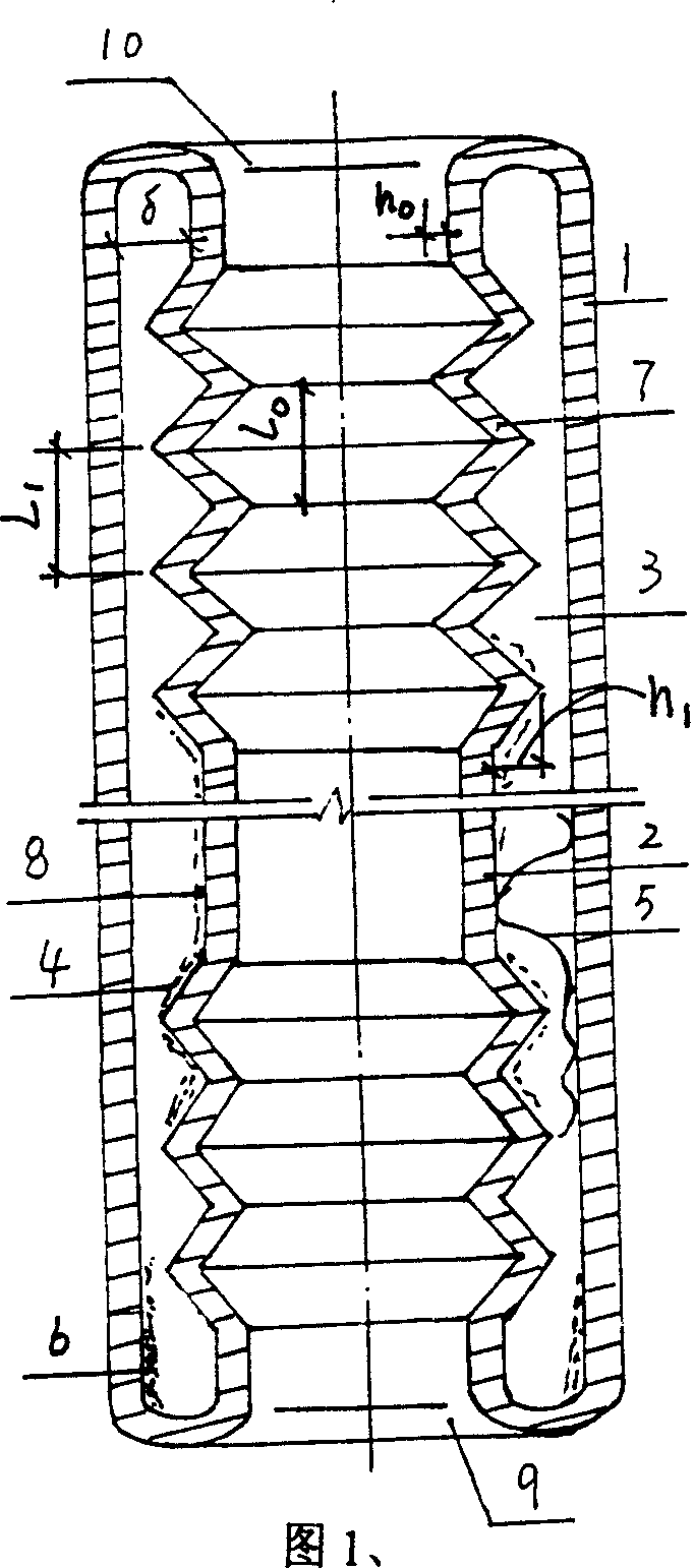
[0013] In conjunction with the attached drawings, it is further explained in detail; in the figure, 1 shows the outer glass tube, 4 shows the absorbing coating, 5 shows the elastic support, 6 shows the getter, and 9 and 10 respectively show the inlet and outlet of the heat transfer medium in the tube. Export.

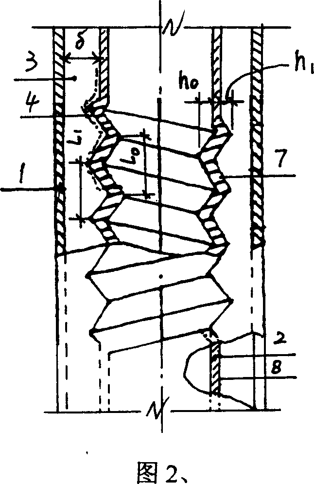
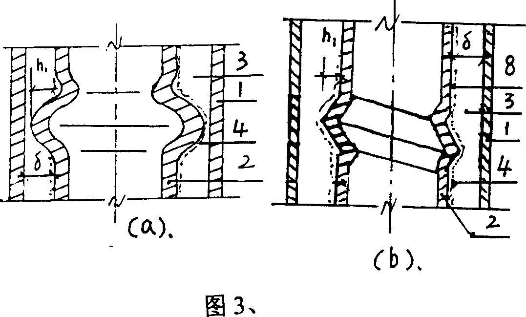
[0014] As shown in Figures 1 and 2, the corrugated body or threaded body of the inner glass tube 2 is distributed in a continuous or discontinuous group of corrugations 7, and each group of corrugations 7 contains at least one annular corrugation body , generally containing 1 to 6 ring wave protrusions.

[0015] As shown in Figure 1, there is one or two group-shaped wave protrusions 7 near one end of the inner glass tube 2, or one or two assembled wave protrusions 7 are respectively provided at its two ends, the wave protrusions Body 7 is a corrugated or threaded body.

[0016] As shown in FIG. 2 , there are 1 to 4 group-shaped corrugations 7 in the middle of the inne...


PUM


Abstract

A glass vacuum solar heat collection tube of through two-end type consists of external glass tube, internal tube with corrugated body, absorption coated layer, elastic support and degasser. It is featured as setting space between two said tubes to be vacuum cavity, melt-jointing two ends of two said tubes to be an integral body for sealing two ends with each other and setting circular wave form ledges on internal tube to be distributed in mode of group wave ledges being not continuously set.

Description

technical field [0001] The invention belongs to the field of solar energy utilization devices, and relates to a double-end straight-through all-glass vacuum solar heat collection tube. Background technique: [0002] In the prior art, in the solar water heater industry, the glass vacuum tube solar water heater is the leading product, and the all-glass vacuum solar heat collector tube is its core component. This kind of heat collector tube consists of an inner glass tube, an outer glass tube, and a selective absorption layer. It is composed of spring bracket, getter and other accessories. The inner and outer glass tubes are welded together in a sealed and integrated manner with only the ports at one end of the inner and outer glass tubes. There is a vacuum chamber between the two, and the spring bracket located in the cavity supports the inner glass tube. , so that it can be freely expanded and contracted to buffer the stress changes caused by thermal expansion and contraction...

Claims


Application Information

Patent Timeline
Patent Type & Authority Applications(China)
IPC IPC(8): F24J2/05F24J2/26F24S10/40F24S10/75
CPCY02E10/44F24J2/055F24S10/45
Inventor 罗赞继于学德程翠英
Owner 罗赞继
Why Eureka
Try Eureka