Stepping motor

A technology of stepping motors and rotating shafts, applied in the field of screw rods, can solve the problems of self-starting frequency and drop that have not been raised, and achieve the effects of improving motor characteristics, reducing inertial loads, and preventing the decline of the maximum self-starting frequency

A technology of stepping motors and rotating shafts, applied in the field of screw rods, can solve the problems of self-starting frequency and drop that have not been raised, and achieve the effects of improving motor characteristics, reducing inertial loads, and preventing the decline of the maximum self-starting frequency

CN1961469AInactive Publication Date: 2007-05-09SANKYO SEIKI MFG CO LTD

Image

  • Stepping motor
  • Stepping motor
  • Stepping motor

Examples


Embodiment Construction

[0048] Next, the best mode for carrying out the present invention will be described with reference to the drawings.

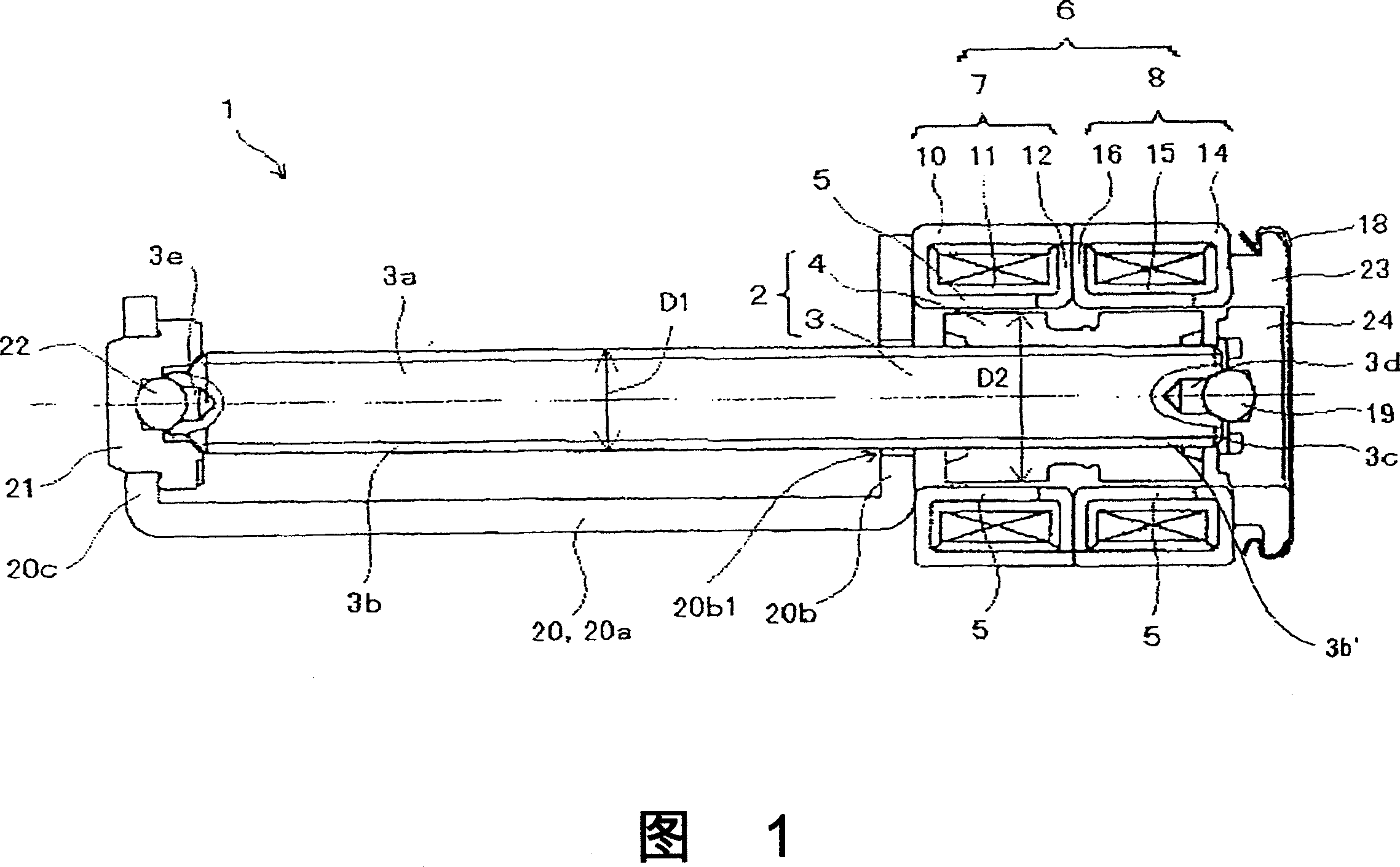
[0049] Fig. 1 is a side sectional view showing a stepping motor according to an embodiment of the present invention.

[0050] (Structure of stepping motor)

[0051] The stepping motor 1 of this form is a so-called PM-type stepping motor, and has a rotor 2, a stator 6 and a frame 20, and the rotor 2 has a rotating shaft 3 and a cylindrical permanent magnet 4, and the stator 6 has a radial direction. The pole teeth 5 opposite to the permanent magnets 4 , the frame 20 are on the output side of the rotating shaft 3 and mounted on the stator 6 . Further, on the output side of the rotary shaft 3, an output shaft 3a protruding from the stator 6 is integrally formed, and a screw part 3b is formed on the output shaft 3a. In addition, a bearing holding member 23 is attached to the opposite output side of the stator 6 (the base end 3 c side of the rotating shaft 3 ), an...


PUM


Abstract

A small-sized stepping motor in which its rotary shaft or an output shaft disposed on the output side of its rotary shaft is improved for the purpose of achieving size reduction and motor characteristics improvement. That is, a stepping motor (1) comprises a rotor (2) having a rotary shaft (3) and a permanent magnet (4), and a stator (6) having pole teeth (5) radially opposed to the permanent magnet (4), the rotary shaft (3) being made of aluminium or aluminium alloy. Further, an output shaft (3a) installed on the output side of the rotary shaft (3) so as to project from the stator (6) is made also of aluminium or aluminium alloy.

Description

technical field [0001] The present invention relates to a small stepping motor and a screw part provided on the output side of the rotating shaft. Background technique [0002] As a motor for high-speed movement of a moving object used in an optical head device used in a CD, a DVD player, etc., and a lens group used in a video camera, a stepping motor having a rotor and a stator is known, and the rotor has a rotating shaft 1. The permanent magnet inserted on the outer peripheral side of the rotating shaft, and the stator has pole teeth facing the permanent magnet in the radial direction. Such a stepping motor has, for example, an output shaft protruding from a stator on the output side of the rotating shaft, and a screw shaft portion is formed on the output shaft. The screw part is screwed with a moving body such as an optical head device, and moves the moving body at high speed. [0003] From the viewpoint of miniaturization and thinning of CD, DVD players, and video came...

Claims


Application Information

Patent Timeline
09 May 2007
Publication
CN1961469A
IPC
H02K37/24; H02K7/00
CPC
H02K7/003; H02K1/2786; H02K37/24; H02K1/28; H02K1/2788
Inventors
腰田嘉秋; 山本登子雄