Vortex fluid machinery

A technology of fluid machinery and scroll, applied in mechanical equipment, liquid fuel engines, rotary piston machinery, etc., can solve the problems of no water-jet scroll compressors on the market, reduce leakage, reduce noise, and reduce maintenance costs Effect

Inactive Publication Date: 2011-01-12
柯恩龙 +1
View PDF1 Cites 0 Cited by
  • Summary
  • Abstract
  • Description
  • Claims
  • Application Information

AI Technical Summary

Problems solved by technology

So far no water-injected scroll compressors are available on the market

Method used


Image

  • Vortex fluid machinery
  • Vortex fluid machinery
  • Vortex fluid machinery

Examples


Embodiment Construction

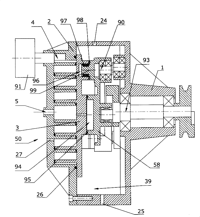
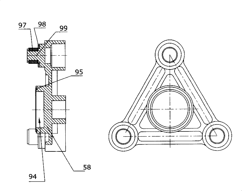
[0025] figure 1 It is a sectional view of an oil-free scroll air compressor according to the first embodiment of the present invention. figure 2 Component diagram for driving the linkage frame for the orbital motion of the compressor. Such as figure 1 As shown, the volume changing device 50 of the compressor includes an orbiting scroll 3 and a fixed scroll 2 . The fixed scroll 2 is connected with the machine base 1 . The drive spindle 93 is rotatably supported on the machine base 1 . The three crankshafts 90, the drive main shaft 93 and the orbital motion drive link frame 58 form a multi-parallelogram mechanism with an anti-rotation function. The three protruding shafts 99 on the orbiting drive link frame 58 are connected with the orbiting scroll 3 via elastic elements 97 to form a closed cavity 96 . The orbiting drive link frame 58 axially supports the orbiting scroll 3 via three thrust washers 98 . Between the orbiting driving link frame 58 and the orbiting scroll 3, ...


PUM


Abstract

The vortex mechanic comprises two fixed vortexes (2A, 2B) on the base (1), with two orbital motion vortex (3A, 3B) fitting with fixed vortexes to form two volume changing device (50A, 50B). Three orbital motion unit (40) set within two volume changing devices with driving power, centrifugal force balance to offset the axle radial thrusting and prevent the self rotation of the orbital motion vortex. Both between two volume change device and orbital motion unit sets, there is a decompression cavity (39A, 39B). When it runs, some liquid spray to the volume change device to seal, lubricate or cool. Liquid discharged from the volume changing device enters into two decompression cavity for storage and releasing. Thrust offset shaft (20) and orbital motion vortex connects with a spring, making the orbital motion vortex having radial and axle displacement compensation function. This displacement compensation and spraying technique can also be used to single vortex fluid mechanics.

Description

technical field [0001] The present invention relates to a scroll (scroll) fluid machine, which can be used as a compressor, a vacuum pump, an expander, and the like. technical background [0002] The scroll fluid machinery adopting the parallelogram anti-rotation mechanism has the advantages of stable and reliable operation, and can be applied to the field of oil-free lubrication. However, the orbital radius is fixed, and the meshing between the scrolls cannot be compensated radially or axially (radial, tip compliant). The machining accuracy of the scroll parts is required to be high, which increases the manufacturing cost of the machine. [0003] US Patents 4,300,875 and 5,752,816 disclose the use of elastic connections in multi-parallelogram anti-rotation mechanisms to realize radial displacement compensation of orbiting scrolls. However, the relationship between the driving crankshaft mentioned in the patent and the crankshaft (idlecrank shaft) constituting the anti-rot...

Claims


Application Information

Patent Timeline
IPC IPC(8): F04C18/02
CPCF01C1/0223F01C21/001
Inventor 柯恩九柯即
Owner 柯恩龙
Why Eureka
Try Eureka