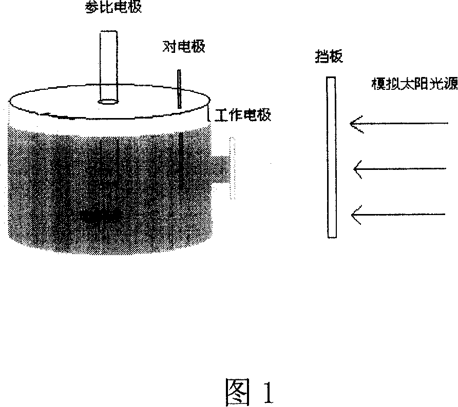
A zinc oxide thin film for solar battery and manufacture method
A zinc oxide thin film and solar cell technology, applied in the field of solar cells, can solve the problems of complex preparation method, unfavorable scale production, poor current characteristics, etc., and achieves the effects of simple process, low cost, and reduced compounding
- Summary
- Abstract
- Description
- Claims
- Application Information
AI Technical Summary
Problems solved by technology
Method used
Image
Examples
Embodiment 1
[0019] Embodiment 1: adopt radio frequency magnetron sputtering to prepare zinc oxide film, substrate adopts the glass (resistivity 5 * 10 -4 Ω·cm), respectively, after six steps of ultrasonic cleaning with detergent, deionized water, acetone, deionized water, alcohol, and deionized water, each for 10 minutes. The target material is a sintered zinc oxide ceramic target (purity is 99.99%, diameter is three inches), and the distance between the target and the substrate is 10 cm. The back vacuum of the sputtering chamber is 5×10 -4 Pa. The working gas is argon (99.99% pure), and the gas flow is controlled at 50 sccm. The sample holder keeps rotating to improve the uniformity of the film. The working pressure is 0.6 Pa, the substrate temperature is 250° C., the sputtering power is 150 W, and the sputtering time is 120 minutes. The test bias voltage is 60mV, and the photocurrent intensity of the double-layer thin film is 15μA.
Embodiment 2
[0020] Embodiment 2: adopt radio frequency magnetron sputtering to prepare zinc oxide film, substrate adopts the glass (resistivity 5 * 10 -4 Ω·cm), respectively, after six steps of ultrasonic cleaning with detergent, deionized water, acetone, deionized water, alcohol, and deionized water, each for 10 minutes. The target material is a sintered zinc oxide ceramic target (purity is 99.99%, diameter is three inches), and the distance between the target and the substrate is 12 cm. The back vacuum of the sputtering chamber is 5×10 -4 Pa. The working gas is argon (99.99% pure), and the gas flow is controlled at 50 sccm. The sample holder keeps rotating to improve the uniformity of the film. The working pressure is 0.8 Pa, the substrate temperature is 150° C., the sputtering power is 200 W, and the sputtering time is 100 minutes. The test bias is 60mV. The measured photocurrent intensity of the double-layer thin film is 10 μA.
Embodiment 3
[0021] Embodiment 3: adopt radio frequency magnetron sputtering to prepare zinc oxide thin film, substrate adopts the glass (resistivity 5 * 10 -4 Ω·cm), respectively, after six steps of ultrasonic cleaning with detergent, deionized water, acetone, deionized water, alcohol, and deionized water, each for 10 minutes. The target material is a sintered zinc oxide ceramic target (purity is 99.99%, diameter is three inches), and the distance between the target and the substrate is 15 cm. The back vacuum of the sputtering chamber is 5×10 -4 Pa. The working gas is argon (99.99% pure), and the gas flow is controlled at 50 sccm. The sample holder keeps rotating to improve the uniformity of the film. The working pressure is 2 Pa, the substrate temperature is 350° C., the sputtering power is 150 W, and the sputtering time is 60 minutes. The test bias is 60mV. The measured photocurrent intensity of the double-layer thin film is 6.5μA.
PUM
| Property | Measurement | Unit |
|---|---|---|
| thickness | aaaaa | aaaaa |
| particle size | aaaaa | aaaaa |
| mean roughness | aaaaa | aaaaa |
Abstract
Description
Claims
Application Information
 - R&D
- Intellectual Property
- Life Sciences
- Materials
- Tech Scout
- Unparalleled Data Quality
- Higher Quality Content
- 60% Fewer Hallucinations
Browse by: Latest US Patents, China's latest patents, Technical Efficacy Thesaurus, Application Domain, Technology Topic, Popular Technical Reports.
© 2025 PatSnap. All rights reserved.Legal|Privacy policy|Modern Slavery Act Transparency Statement|Sitemap|About US| Contact US: help@patsnap.com

