Normal pressure air suction type operation and cooling fuel cell

A fuel cell and inhalation technology, applied in fuel cells, fuel cell additives, fuel cell heat exchange, etc., can solve the problems of large volume, high cost, heavy weight, etc., to reduce volume and weight, save materials, and facilitate assembly easy simple effect

Active Publication Date: 2007-05-16
SHANGHAI MUNICIPAL ELECTRIC POWER CO +1
View PDF0 Cites 4 Cited by
  • Summary
  • Abstract
  • Description
  • Claims
  • Application Information

AI Technical Summary

Problems solved by technology

[0012] The defect of the above-mentioned fuel cell is that a fan is required on the collecting end face of the air guide groove of each fuel cell module, and each fan consumes the power of the fuel cell itself, and the combined battery modules are large in size and heavy in weight. heavy, high cost

Method used


Image

  • Normal pressure air suction type operation and cooling fuel cell
  • Normal pressure air suction type operation and cooling fuel cell

Examples


Embodiment

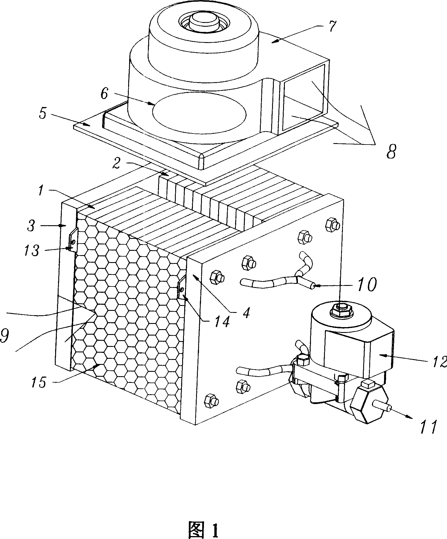
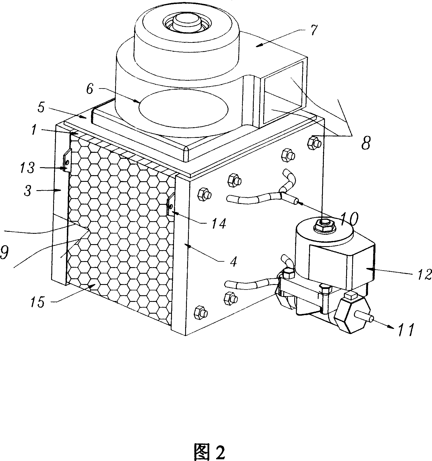
[0026] As shown in Figure 2, it is a normal-pressure air-inhaled operation and cooling fuel cell power generation system composed of two fuel cell modules. Including membrane electrode, diversion plate, current collector motherboard, front and rear end plates, fastening rods, and air and hydrogen supply device, the air supply device includes a shared fan 7, air collecting cover 5, the hydrogen supply device It includes a hydrogen storage tank (not shown in the figure), a hydrogen exhaust solenoid valve 12, hydrogen enters from 10, and is discharged from 11. Since the fan is suction type, the negative pressure is generated by the action of the air collecting cover 5, and the air enters from the end faces of the air passages of the two fuel cell modules covered with a layer of air filter 15, and then is discharged from the fan outlet 8. The power of such a fuel cell power generation system can reach 200-400W, which is twice the power of a single fuel cell power generation system...


PUM


Abstract

The related normal-air suction fuel cell comprises: two cell modules shared one front and back end, a set of air supply device on module top, and a set of hydrogen supply device connected with hydrogen inlet and outlet on module ends. Wherein, the air exhaust ends of two modules are set oppositely to form a channel. Compared with prior art, this invention is low cost and compact, and needs less power consumption.

Description

technical field [0001] The invention relates to a fuel cell, in particular to a normal-pressure air suction type operation and cooling fuel cell. Background technique [0002] An electrochemical fuel cell is a device that converts hydrogen and oxidants into electrical energy and reaction products. The internal core component of the device is the membrane electrode (Membrane Electrode Assembly, referred to as MEA). The membrane electrode (MEA) is composed of a proton exchange membrane and two porous conductive materials, such as carbon paper, sandwiched between the two sides of the membrane. On the two boundary surfaces of the membrane and the carbon paper, there are even and finely dispersed catalysts for initiating electrochemical reactions, such as metal platinum catalysts. Conductive objects can be used on both sides of the membrane electrode to draw the electrons generated during the electrochemical reaction through an external circuit to form a current loop. [0003] ...

Claims


Application Information

Patent Timeline
Patent Type & Authority Applications(China)
IPC IPC(8): H01M8/06H01M8/04H01M8/00H01M8/04014H01M8/04082H01M8/04089H01M8/0606
CPCY02E60/50
Inventor 胡里清葛栩栩王立明徐大清李创蔡建军
Owner SHANGHAI MUNICIPAL ELECTRIC POWER CO
Why Eureka
Try Eureka