Battery pack protecting circuit and battery pack

A technology for protecting circuits and battery components, applied to battery circuit devices, emergency protection circuit devices, electrical components, etc., can solve problems such as high temperature, uncontrollable, and inability to perform protection functions, so as to ensure duplication and reliability performance, the effect of a small number of parts

Inactive Publication Date: 2007-05-16
MURATA MFG CO LTD
View PDF3 Cites 9 Cited by
  • Summary
  • Abstract
  • Description
  • Claims
  • Application Information

AI Technical Summary

Problems solved by technology

Therefore, after the thermal disturbance of the switching element, the temperature of the battery pack as a whole becomes high, and even if the switching element is controlled by the protection control circuit, it may not be able to control
That is, in the protection circuit described in Patent Document 3, since the circuit cannot be protected by detecting local overheating, a sufficient protection function cannot be exhibited.
In addition, conversely, if the protection start temperature is set lower, the protection function may be performed even against overheating to the extent that it is actually not a problem.

Method used


Image

  • Battery pack protecting circuit and battery pack
  • Battery pack protecting circuit and battery pack
  • Battery pack protecting circuit and battery pack

Examples


Embodiment Construction

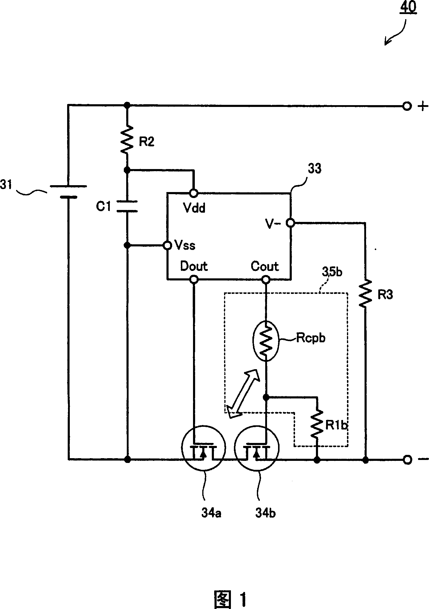
[0058] The configuration of the protection circuit of the battery pack and the battery pack according to the first embodiment will be described based on FIG. 1 .

[0059] FIG. 1 is a circuit diagram of a battery pack provided with a protection circuit for the battery pack. The first switching element 34 a and the second switching element 34 b are provided in series with the charging and discharging path of the battery cell 31 . The ground terminal Vss of the protection control circuit 33 is connected to the negative electrode of the battery cell 31 , and Vdd is connected to the positive electrode of the battery cell 31 via the resistor R2 . In addition, a capacitor C1 for removing noise signals is connected between Vdd and Vss. In addition, a resistor R3 is connected between the V− terminal of the protection control circuit 33 and the negative (−) terminal of the battery pack 10 .

[0060] The first / second switching elements 34a, 34b are each composed of FETs. The protectio...


PUM


Abstract

There are provided a first switch element (34a) for interrupting the discharging current following in a battery cell (31) and a second switch element (34b) for interrupting the charging current. A positive character thermistor (Rcpb) is inserted between a gate control terminal (Dout,Cout) of a protection control circuit (33) and the gate of at least one of the switch elements (34a,34b), while a resistor (R1b) is connected between the gate and source of that switch element. The positive character thermistor (Rcpb) is thermally coupled to the first and second switch elements (34a,34b) or to the battery cell (31). In this way, an extraordinary excessive heating state of the switch elements (34a,34b) or battery cell (31) causes a rise in the resistance of the positive character thermistor (Rcpb), which then places the switch element (34b) in an interruption state to activate a protection function.

Description

technical field [0001] The present invention relates to a protection circuit for protecting a secondary battery from overcurrent or abnormal overheating. Specifically, it relates to a protection circuit for a battery pack using a positive characteristic thermistor and a switching element, and the battery pack. Background technique [0002] Conventionally, in a battery pack used as a power source of a mobile phone or the like, it is required to double the protective mechanism against overcurrent, overheating, and the like. Patent Document 1 shows its configuration as a general method. [0003] FIG. 11 shows an example of the battery pack protection circuit of this patent document 1. As shown in FIG. In FIG. 11 , a battery unit 131 is provided with first / second switching elements 134a and 134b on its charging and discharging path, and a protection control circuit 133 for controlling them is provided. In addition, a protection element 132 composed of a positive characteristic...

Claims


Application Information

Patent Timeline
Patent Type & Authority Applications(China)
IPC IPC(8): H02J7/00H02H7/18
CPCY02E60/12Y02E60/10
Inventor 椿修二池田丰宫川和人
Owner MURATA MFG CO LTD
Why Eureka
Try Eureka