Circuit for measuring synchronized sampler of flying capacitance

A technology of synchronous sampling and flying capacitance, applied in the direction of measuring electricity, measuring electrical variables, measuring current/voltage, etc., can solve the problem of synchronous sampling of multiple signals, ensure measurement accuracy and consistency, and suppress common mode interference , Facilitate the effect of industrialization and engineering

Inactive Publication Date: 2007-05-23
BEIHUA UNIV +1
View PDF0 Cites 17 Cited by
  • Summary
  • Abstract
  • Description
  • Claims
  • Application Information

AI Technical Summary

Problems solved by technology

[0007] Although this method can realize the isolation of multiple measurement signals, it has the disadvantage that it cannot sample multiple signals synchronously.

Method used


Image

  • Circuit for measuring synchronized sampler of flying capacitance
  • Circuit for measuring synchronized sampler of flying capacitance
  • Circuit for measuring synchronized sampler of flying capacitance

Examples


Embodiment 1

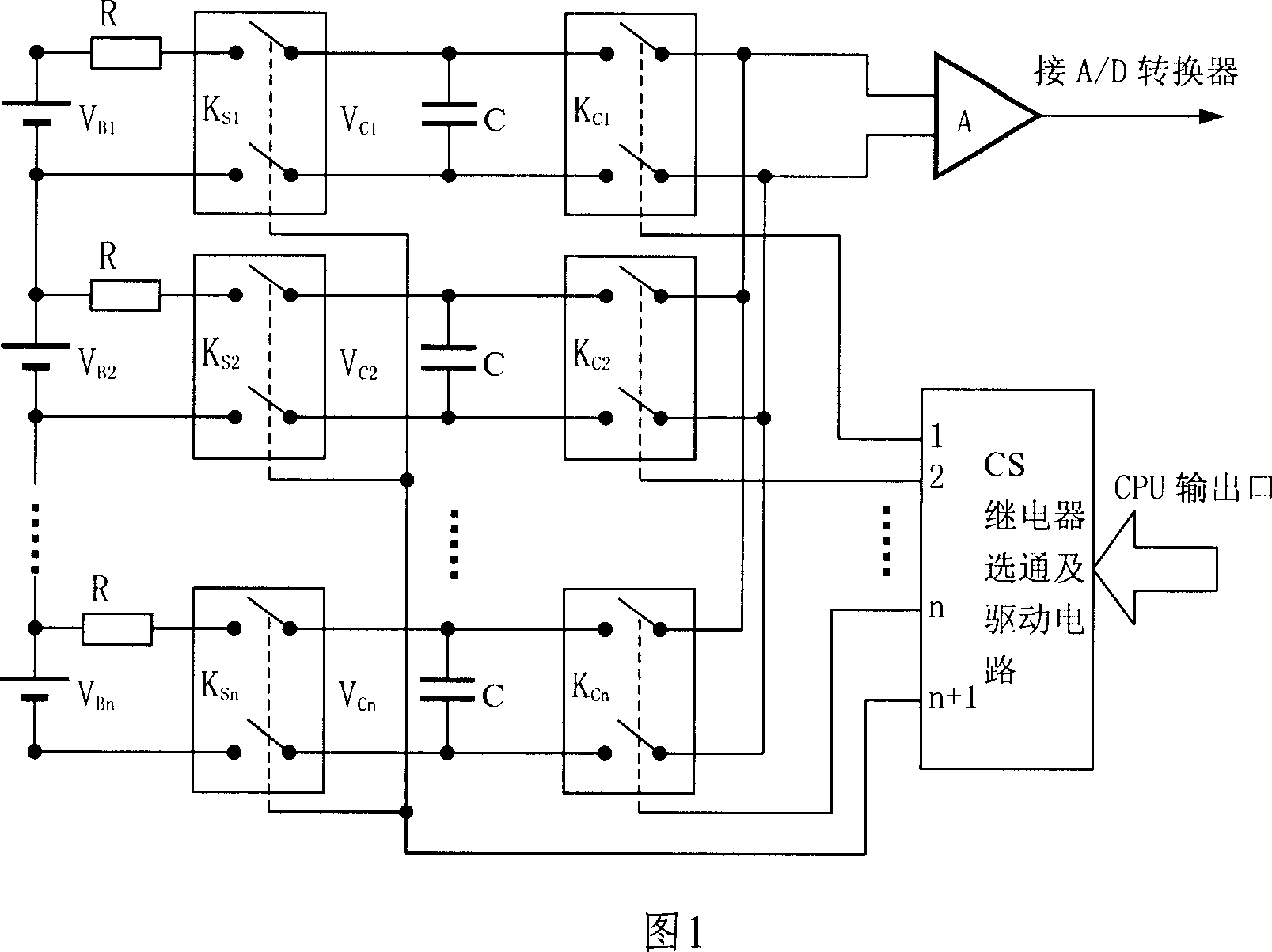
[0075] Number of measurement channels: 15 module battery voltages; voltage measurement range: 0~17V; measurement cycle: 50ms; measurement accuracy: 0.2%; measurement synchronization time: 1ms; the specific implementation plan is as follows:

[0076] The measurement schematic diagram is shown in Figure 1. KS1, KS2, KS3...KS15 and KC1, KC2, KC3...KC15 use AQW614 double-pole double-throw normally open PhotoMOS relays. The withstand voltage at both ends of the switch is 600V. On-resistance ≤ 120Ω, off-leakage current ≤ 1μA, typical on-time 0.5ms, typical off-time 0.2ms.

[0077] The sampling and holding capacitor C is made of polystyrene capacitor, the leakage current is ≤500nA, and the withstand voltage is 60V.

[0078] A is a high-impedance differential operational amplifier, bias current ≤ 2nA, input impedance ≥ 2MΩ.

[0079] Rf1 and Rf2 are used to divide the measuring voltage, Rf1=1.5MΩ, Rf2=500kΩ.

[0080] CS adopts 74LVC15416 to select 1 decoder, and the driving circuit a...

Embodiment 2

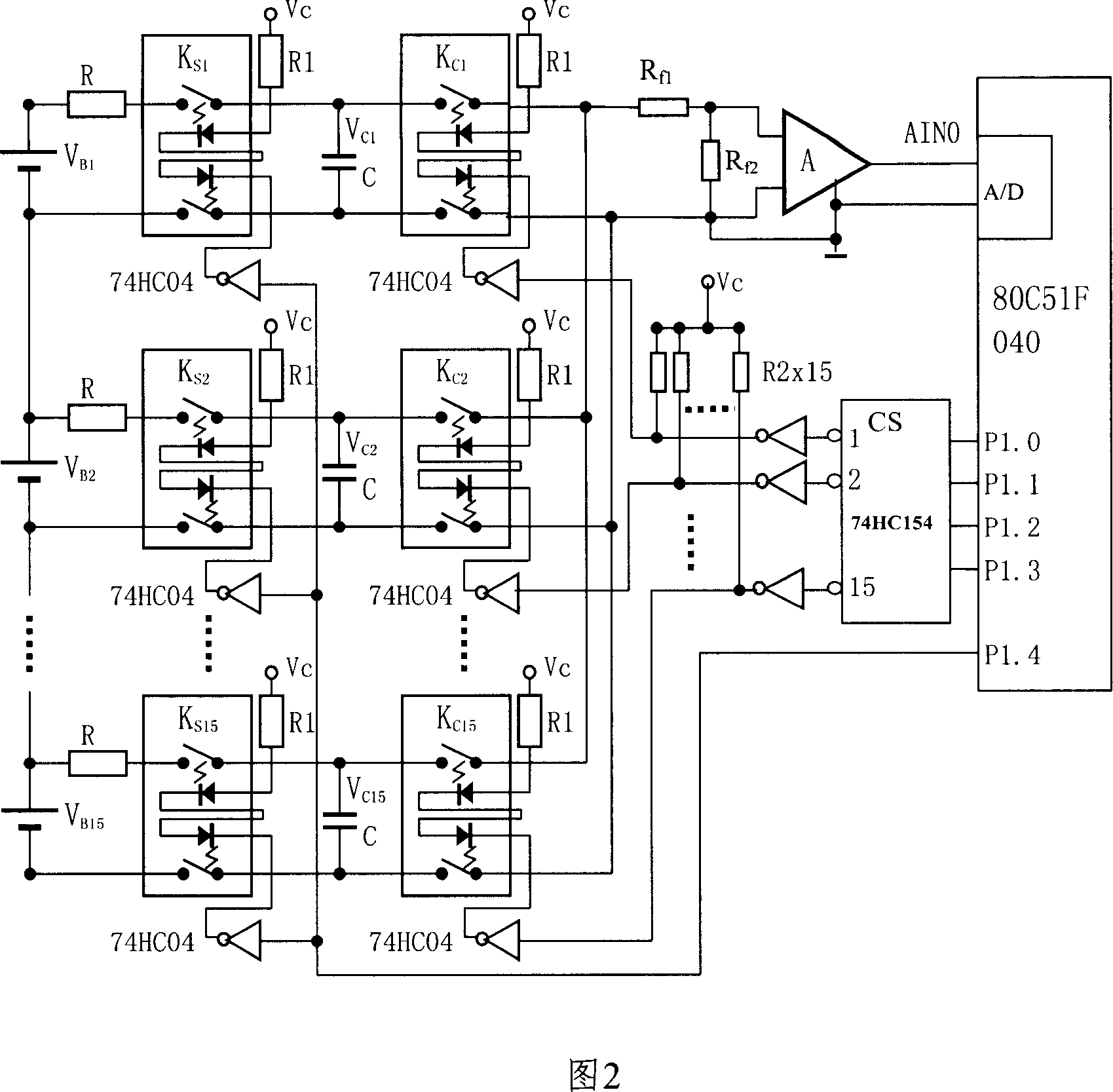
[0098] Single battery voltage measurement 10 channels, measurement range: 0 ~ 2V, measurement accuracy: 0.1%, total voltage measurement 1 channel, measurement range: 0 ~ 20V, measurement accuracy: 0.2%, charging current measurement 1 channel, measurement range: 0 ~100A, measurement accuracy: 0.2%, 1 channel for discharge current measurement, measurement range: 0~100A, measurement accuracy: 0.2%, measurement cycle: 100ms.

[0099] The measurement schematic diagram is shown in Figure 2. The total voltage measurement uses a 0-20V input and 0-5V output voltage transmitter. Charge and discharge current measurement adopts 0-100A input, 0-5V output current transmitter. KS1, KS2, KS3...KS13 and KC1, KC2, KC3...KC13 use AQW210 double-pole double-throw normally open PhotoMOS relay, the withstand voltage at both ends of the switch is 350V, and the on-resistance is ≤35Ω. Turn-off leakage current ≤1μA, typical turn-on time 0.25ms, typical turn-off time 0.05ms.

[0100] The sampling and h...


PUM


Abstract

This invention discloses a flying capacitance synchronous sampling and measurement circuit and method of measurement error correction, including synchronous sampling relay group, each of the two input terminal on a synchronous sampling relay connected to the nodes of a battery module. There is the same amount of AD converter relays fitted with synchronous sampling relay group. Each of the two input nodes of an AD converter is connected to each of the two output nodes of the corresponding synchronous sampling relay, paralleling a sampling maintain capacitance between the two input nodes. The two outputs of an AD conversion relay are connected to the input of a high input impedance differential operational amplifier. After proper evacuation, operational amplifier output signal is transmitted to AD converters. This invention achieves electrical isolated, multiple functional modules battery voltage synchronous sampling. Circuit is simple and high precision, facilitate the measurement channel expansion.

Description

technical field [0001] The invention relates to a technique for isolating and synchronously measuring multi-module voltage and current signals of a power battery pack. Background technique [0002] The measurement of the voltage and current of the power battery pack module needs to overcome the common-mode voltage of nearly hundreds of volts or even hundreds of volts. Isolation measures must be taken to ensure the normal operation of the measurement circuit. [0003] There are two main technologies currently in use: [0004] 1. Use an isolation amplifier to isolate the voltage and current signals of multiple modules. [0005] This method has the disadvantages of high cost, large volume, large nonlinear error, and the need to adjust or calibrate multiple isolation amplifiers. [0006] 2. Using relay array and flying capacitor, signal isolation and measurement are realized through roving sampling. [0007] Although this method can realize the isolation of multiple measureme...

Claims


Application Information

Patent Timeline
Patent Type & Authority Applications(China)
IPC IPC(8): G01R31/36G01R19/00
Inventor 姜丰
Owner BEIHUA UNIV
Why Eureka
Try Eureka