Ultrasonic probe for quantitative measurement of bone mineral density

A bone mineral density and measuring probe technology, which is applied in ultrasonic/acoustic/infrasonic diagnosis, measuring devices, acoustic diagnosis, etc., can solve the problems of high price, low accuracy, and large radiation dose, and achieve low price and high accuracy , small size effect

Inactive Publication Date: 2007-05-30
TIANJIN UNIV
View PDF0 Cites 13 Cited by
  • Summary
  • Abstract
  • Description
  • Claims
  • Application Information

AI Technical Summary

Problems solved by technology

[0004] The technical problem to be solved by the present invention is to overcome the disadvantages of the above-mentioned existing bone density measuring instruments, such as low accuracy, high radiation dose, or high price, which cannot take into account all aspects

Method used


Image

  • Ultrasonic probe for quantitative measurement of bone mineral density

Examples


Embodiment Construction

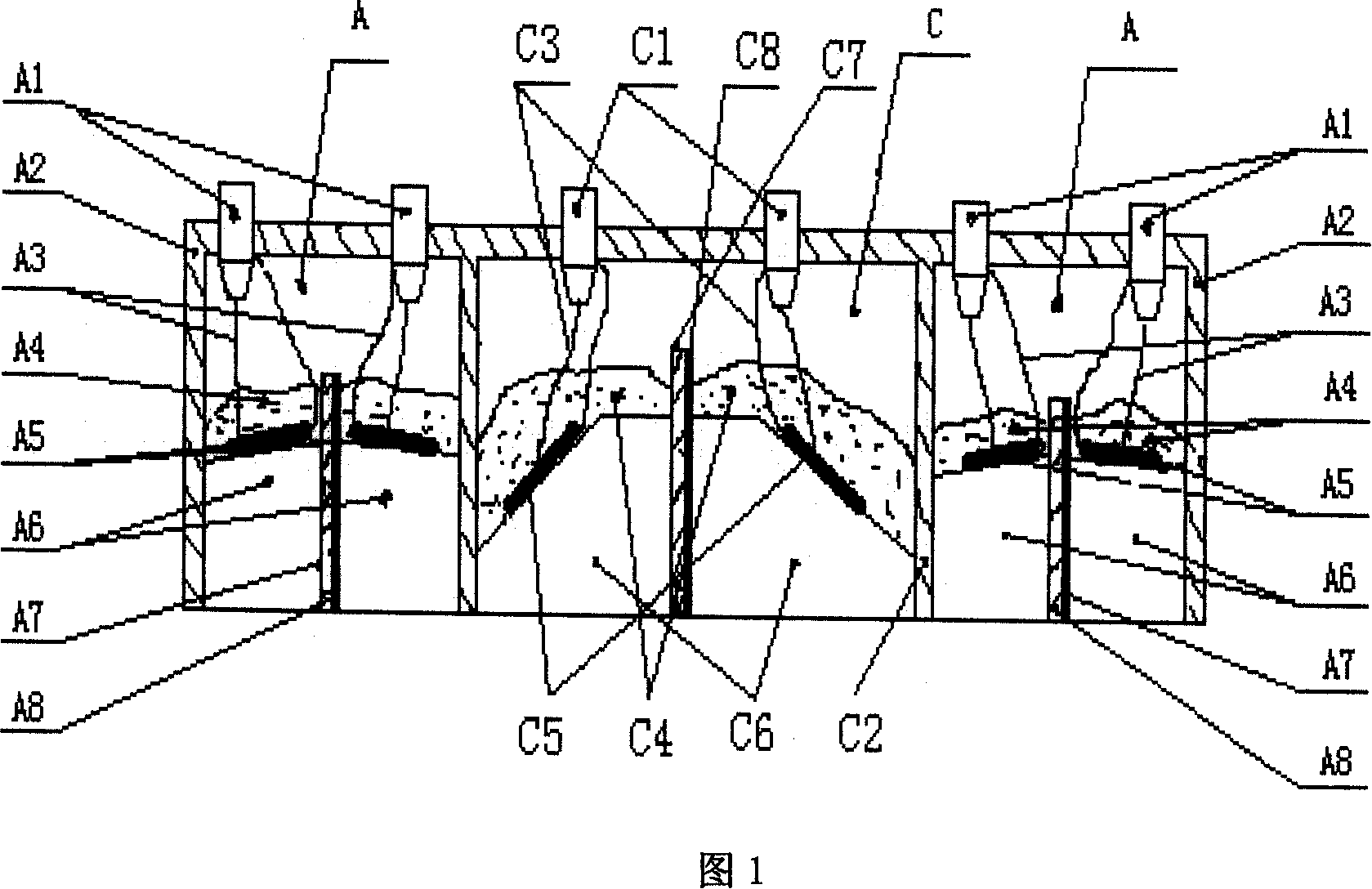
[0022] Now in conjunction with Fig. 1, the specific implementation of the present invention applied to the human tibia quantitative ultrasonic measurement bone density special probe is described as follows:

[0023] As shown in Figure 1, the special probe for tibial quantitative ultrasound measurement of bone density is composed of two positioning probes A and measuring probe C; the two positioning probes have the same structure and are located on both sides of the measuring probe respectively, and the positioning probe and the measuring surface of the measuring probe are parallel.

[0024] The positioning probe A is composed of the shell A2 and the probe core composed of the delay block A6, the wafer A5, the absorption block A4, the copper foil A7 and the sound insulation layer A8; the two wafers A5 are respectively glued to the slopes of the two delay blocks A6 On the top, it is in the shape of a splayed. The chip A5 is made of PZT material with a frequency of 1.25-5 MHz. The...


PUM


Abstract

The invention discloses an ultrasonic probe of bone-ore density, which consists of detecting probe and two directional probes, wherein the detecting probe and directional probe are composed of case, delaying block in the case, wafer, acoustic layer, copper foil and adsorbing block. The invention can meter the spreading time and speed in the bone, which is relative to bone-ore to judge bone quality.

Description

technical field [0001] The invention relates to an instrument for measuring bone mineral density, in particular to a probe for measuring bone mineral density. Background technique [0002] Osteoporosis is an insidious disease that seriously endangers the health of the elderly. my country is the country with the largest elderly population in the world. The elderly over 60 years old have reached 130 million, accounting for 10% of the total population. About 50% of elderly women and 20% of elderly men in China suffer from osteoporosis. Its prevention is extremely urgent. [0003] At present, the early diagnosis of osteoporosis is to use X-ray machine to measure bone density. Although this instrument is simple and practical, it has no quantitative function and has low sensitivity. In the 1980s, a single-photon absorption measuring instrument was used, using americium as a radioactive source. Although this instrument is quick and easy to use and low in cost, it is only suitable ...

Claims


Application Information

Patent Timeline
Patent Type & Authority Applications(China)
IPC IPC(8): A61B8/00G01N29/24
Inventor 万柏坤刘庆凯
Owner TIANJIN UNIV
Why Eureka
Try Eureka