Split type omnibearing take-over laser booster

An all-round and separate technology, which is applied in the direction of combustion method, aerospace vehicle propulsion system device, combustion ignition, etc., can solve the problems of energy loss, limited adjustment range, and failure of optical mirror, so as to achieve small light loss and reduce development The effect of cost and simple structure

Inactive Publication Date: 2007-05-30
UNIV OF SCI & TECH OF CHINA
View PDF0 Cites 10 Cited by
  • Summary
  • Abstract
  • Description
  • Claims
  • Application Information

AI Technical Summary

Problems solved by technology

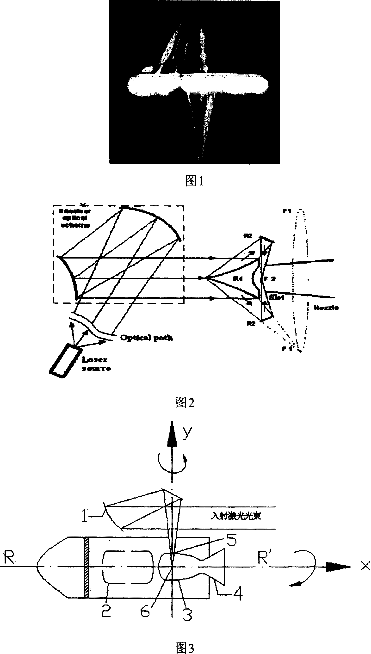
This type of design is shared by the focusing mirror and the nozzle of the thrust chamber, but has the following disadvantages: (1) The laser beam is coaxial with the thruster, and it is difficult to change the incident direction of the laser, which is not conducive to receiving laser beams incident from different azimuths and changing Flight direction; (2) It is difficult to achieve the optimum due to taking into account two points, such as focusing requires a parabolic shape, but as the thrust chamber and nozzle, the parabolic expansion is not necess

Method used


Image

  • Split type omnibearing take-over laser booster
  • Split type omnibearing take-over laser booster
  • Split type omnibearing take-over laser booster

Examples


Example Embodiment

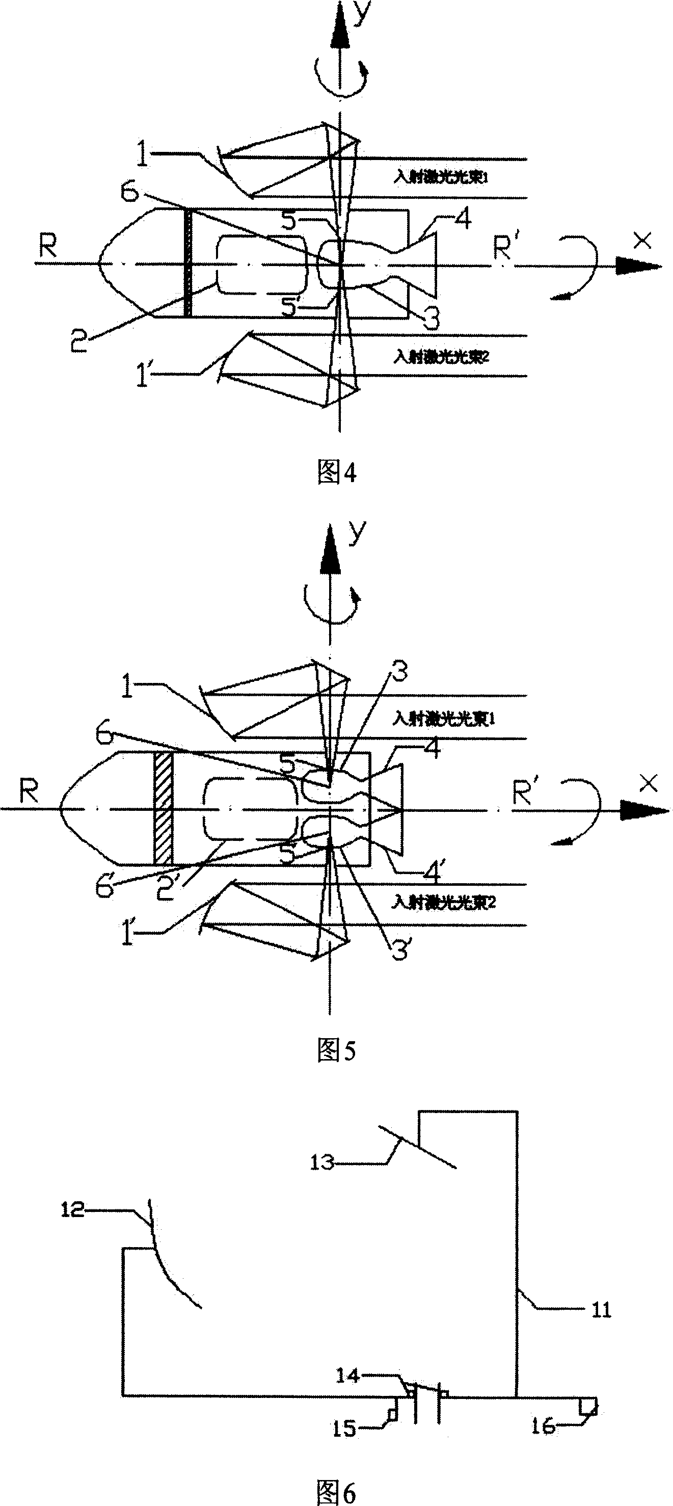
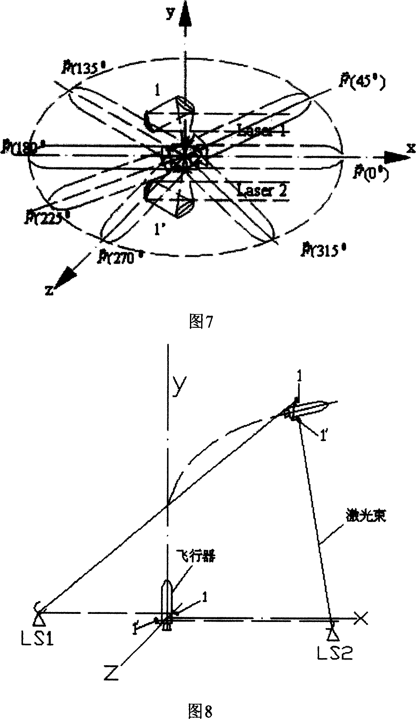
[0027] The present invention has three structural forms, the structure adopting the single beam engine, the structure adopting the double beam single engine and the structure adopting the double beam double engine, which will be described in detail below.

[0028] As shown in Figure 3, the thruster of the present invention adopts a single-beam engine structure. It is composed of an optical system 1, a propellant tank 2, a combustion chamber 3 and a nozzle 4. The optical system 1 is located on the outer side of the combustion chamber 3. , And is connected to the solid body of the arrow body. A transparent circular laser incident window 5 is opened on the combustion chamber 3. The optical system 1 rotates around the laser incident window to realize receiving all the laser beams in the xz plane. When the laser beam passes vertically When the laser incident window 5 is concentrated and incident on the central position 6 of the combustion chamber 3, it ignites the propellant in the com...


PUM


Abstract

The separate omnibearing laser receiving thruster comprises one or two optical systems, thrusting agent storage boxes, one or two burning chambers and spraying tubes, with the optical system at one side of the burning chamber, whose one side opens a transparent laser entrance portal, based on which, the optical system rotating and receiving all the laser beam of XY surfaces, accumulating to the center of the burning chamber through the optical system, with the trusting agent sprayed from the spray tube to generate forward thrusting. Complete separation of the optical system and the thrust system, free from the influence of high temperature and pressure thrust air flow, omnibearingly receiving laser beams from every direction, to adapt to all kinds of track conditions.

Description

technical field [0001] The invention relates to laser propulsion technology in the field of aerospace propulsion technology, in particular to a separate omnidirectional receiving laser thruster. Background technique [0002] In the field of aerospace propulsion technology, how to reduce launch costs and increase payloads has always been a hot spot in research and development. Traditional satellite launches require large-scale chemical launch vehicles. Fuel accounts for a large proportion of the launch weight, and the proportion of payloads in orbit is only about 1.5%. The launch cost is as high as $10,000 / kg, and the pollution is large. Taking my country's first artificial satellite as an example, "Dongfanghong" weighs 173kg. If 1.5% of the payload is used, the actual launch weight is: 11533kg. It can be seen that most of the energy is used to propel the propellant itself, resulting in energy loss. waste. Therefore, scientists have been exploring for a long time, seeking to...

Claims


Application Information

Patent Timeline
IPC IPC(8): B64G1/40F23Q13/00
Inventor 唐志平张庆红
Owner UNIV OF SCI & TECH OF CHINA
Why Eureka
Try Eureka