
Crusher

A pulverizer and pulverizing chamber technology, applied in grain processing, etc., can solve the problems of fire, fan speed reduction, material change performance, etc., to achieve the effect of expanding the processing range, reducing power consumption, and reducing raw material requirements

Inactive Publication Date: 2007-06-06
李福全
View PDF0 Cites 15 Cited by
  • Summary
  • Abstract
  • Description
  • Claims
  • Application Information

AI Technical Summary

Problems solved by technology

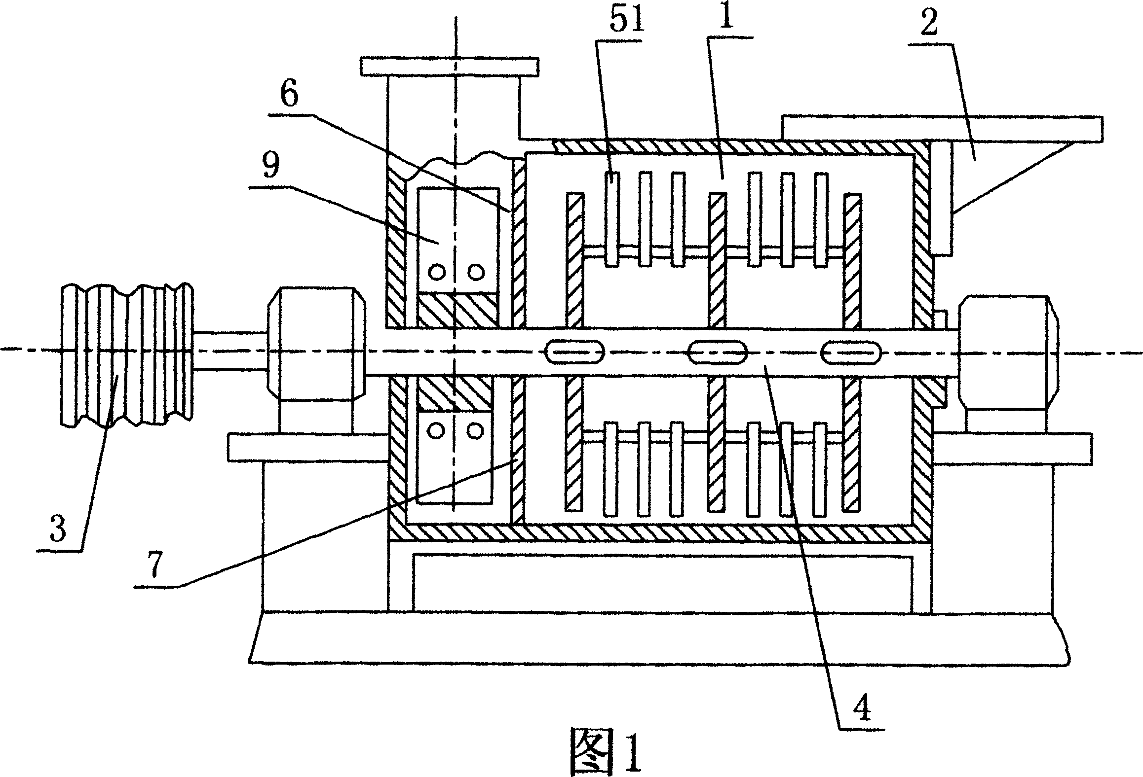
The disadvantages of this device are: ①The fan is located outside the screen of the discharge port, and is directly mounted on the end of the main shaft to be driven by the main shaft. The suction power is not strong enough, the output rate is low, and the power consumption is large
②The water content of the material is required to be low (generally below 2% to 15%). When the material is wet, the mesh of the screen is easily blocked, and because the suction force generated by the fan is not strong enough, the material is not easy to be sucked out, and it will Staying in the crushing room for a long time, on the one hand, due to the long crushing processing time, it is easy to cause the material to overheat and change its performance and even catch fire, often causing fires; on the other hand, the original unsucked material is mixed with the new material that is continuously added Accumulation causes severe clogging of the crushing chamber cavity, which reduces the spindle speed. The reduction of the spindle speed also reduces the fan speed, the suction generated by the fan is further reduced, and the screen cannot be dredged. Therefore, the power equipment that drives the spindle is greatly overloaded. Not only Waste a lot of power, damage the power transmission belt, and even burn the motor in severe cases
③The crushing chamber is only provided with a discharge port on one side, and the materials located in the middle of the crushing chamber and the other side need to go through a long road to reach the discharge port, not only blocked by the materials in front, but also by the rotating crushing tool Blocking, so the output speed is very slow

Method used


Image

  • Crusher
  • Crusher
  • Crusher

Examples


Embodiment Construction

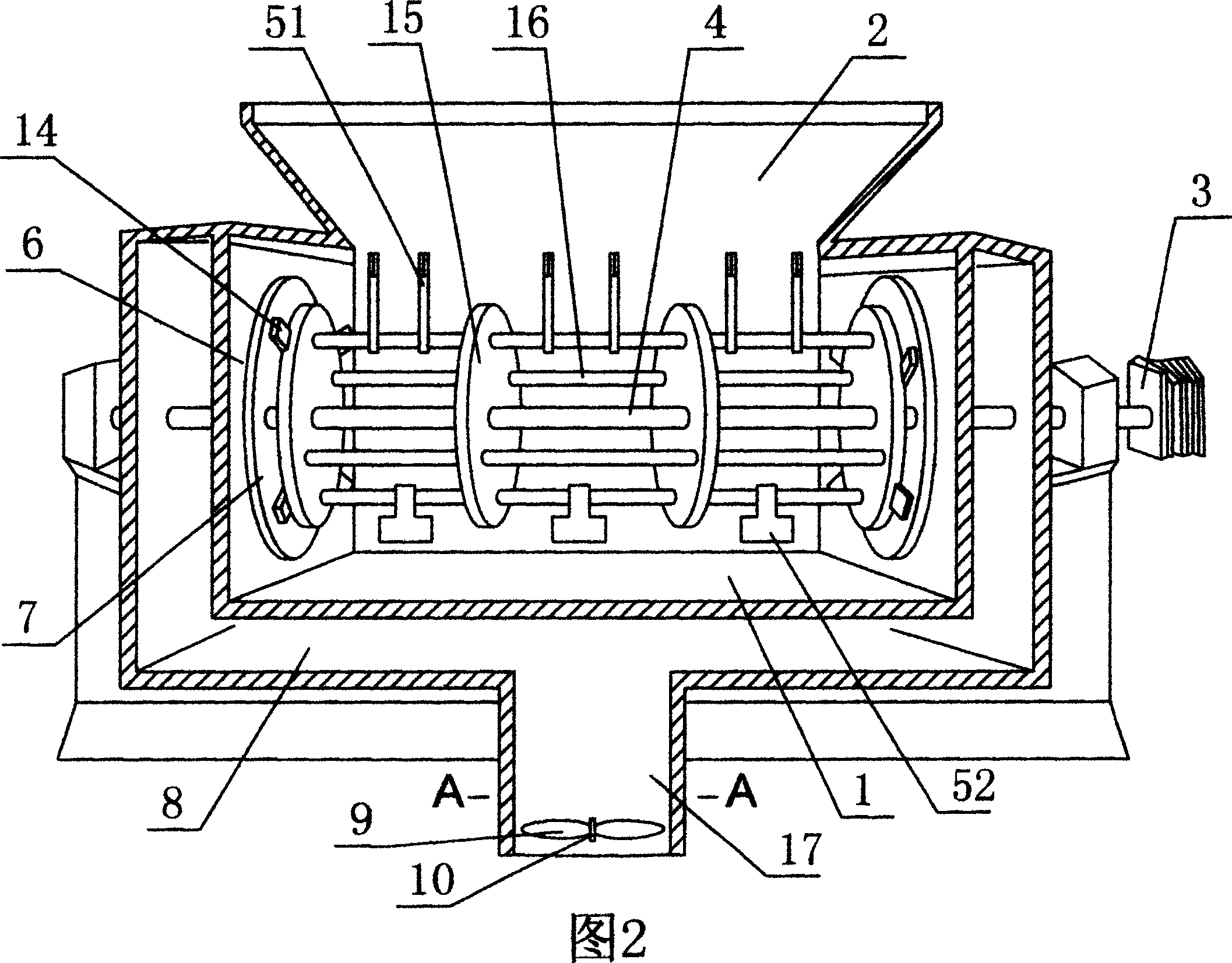
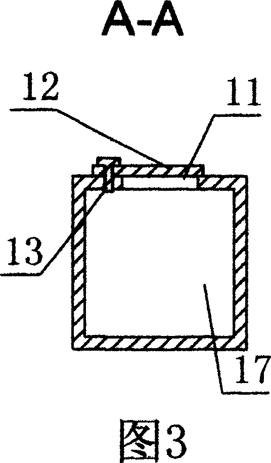
[0019] The specific embodiment of the present invention includes a material crushing chamber 1, a feed inlet 2 is arranged above the crushing chamber, a main shaft 4 driven by a power device 3 is provided in the chamber of the crushing chamber, and the main shaft can be driven to rotate in a plane perpendicular to the axis of the main shaft. The pulverizing cutter 51 or 52, at least one of the two axial ends of the pulverizing chamber is provided with a discharge port 6, and a screen 7 is provided on the discharge port, and it is characterized in that: the periphery of the pulverizing chamber is also provided with a discharge port. The mouth is connected to the suction chamber 8, and the outlet 17 of the suction chamber is provided with an induced fan 9, and the power shaft 10 of the induced fan is not connected with the main shaft 4 for transmission.

[0020] The side wall of the outlet of the suction chamber is provided with an air introduction port 11 and an adjustable dampe...


PUM


Abstract

The crusher includes one material crushing chamber with feeding port in the upper part, one spindle driven with power unit inside the crusher, one crushing cutter capable of rotating in the plane perpendicular to the main axis, and at least one discharging port with strainer. It features the suction chamber communicated with the discharging port and the induced draft fan in the outlet of the suction chamber with driving shaft not connected to the spindle. The present invention has increased outwards discharging suction force, no chocking of the strainer and high discharging speed and output.

Description

technical field [0001] The invention relates to a pulverizer, which can be used for pulverizing and processing various materials, such as: limestone, coal, non-explosive mineral materials, sawdust containing fiber materials, bamboo and wood powder, Chinese herbal medicine, rice bran and the like. Background technique [0002] The general pulverizer currently on the market is shown in Figure 1. Its structure basically consists of a material pulverization chamber 1, a main shaft 4 that is located in the pulverization chamber cavity and driven by a power device 3, and can be rotated in a plane perpendicular to the axis of the main shaft. It is composed of a crushing tool driven by the main shaft. There is a feed port 2 on the upper side of the crushing chamber, and a discharge port 6 is provided on the axial end of the crushing chamber opposite to the feed port. A screen is provided on the discharge port. 7. A fan 9 coaxially driven by the main shaft is arranged outside the scr...

Claims


Application Information

Patent Timeline
IPC IPC(8): B02C13/286B02C13/288B02C13/284B02C13/28B02C13/02B02C18/22B02C18/18B02C18/16B02C18/14
Inventor 李福全
Owner 李福全
Learn More