Trailer

A sub-frame and suspension technology, which is applied in the direction of motor vehicles, vehicle parts, traction connectors, etc., can solve the problems of large volume, high center of gravity, poor stability, etc., and achieve more energy storage, reliable connection, and stable maintenance running effect

Inactive Publication Date: 2007-06-06
北京军适机械有限公司
View PDF0 Cites 4 Cited by
  • Summary
  • Abstract
  • Description
  • Claims
  • Application Information

AI Technical Summary

Problems solved by technology

The existing trailers have the following problems: 1. Traditional trailers generally use leaf spring suspension as the trailer suspension device to connect the car body and wheels, which have a large volume, high center of gravity of the car body, and poor stability; This problem can be better solved, but the general torsion shaft is a circular torsion bar, the torsion angle of the circular torsion bar is small, and the overall torsion bar has small elasticity and energy storage
But this kind of braking device has a shortcoming, exactly when the car is reversing, the tractor is backward, and the traction main shaft will also be subjected to a backward thrust, and it will also start the opening mechanism to stretch the two brake shoes, so that the trailer is braked. Therefore, most trailers using inertial braking devices cannot reverse normally
3. When the trailer is connected to the tractor, it is necessary to connect the tail light socket at the tail of the tractor with the plug of the trailer tail light system to ensure the normal use of the trailer tail light. The plug and socket of the tractor and the trailer are compatible with each other, but when the tractor and the trailer are of different models, the taillight socket and the plug may not match and cannot be directly connected to work normally, such as the commonly used Dongfeng, Jiefang, For the three models of Steyr, the taillight sockets and plugs of each model are different, and they cannot be plugged and used at will; at the same time, the output voltage of the power system of each model is not the same, which greatly limits the trailers of various models. Interchangeable use with tractors

Method used


Image

  • Trailer
  • Trailer
  • Trailer

Examples


Embodiment Construction

[0024] The present invention will be described in detail below in conjunction with the accompanying drawings and embodiments.

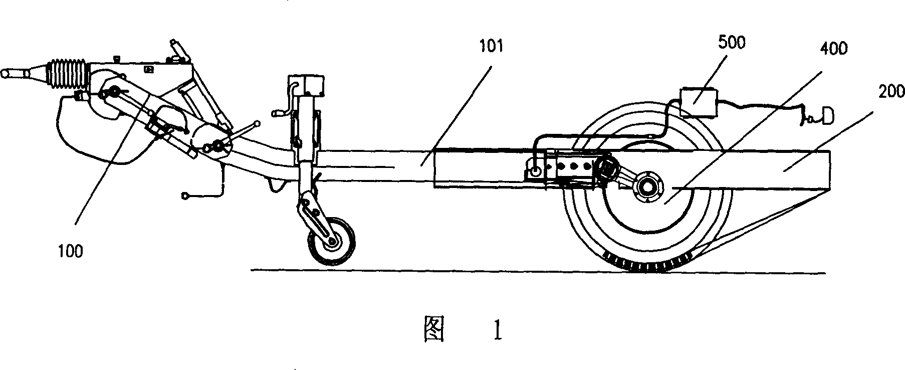
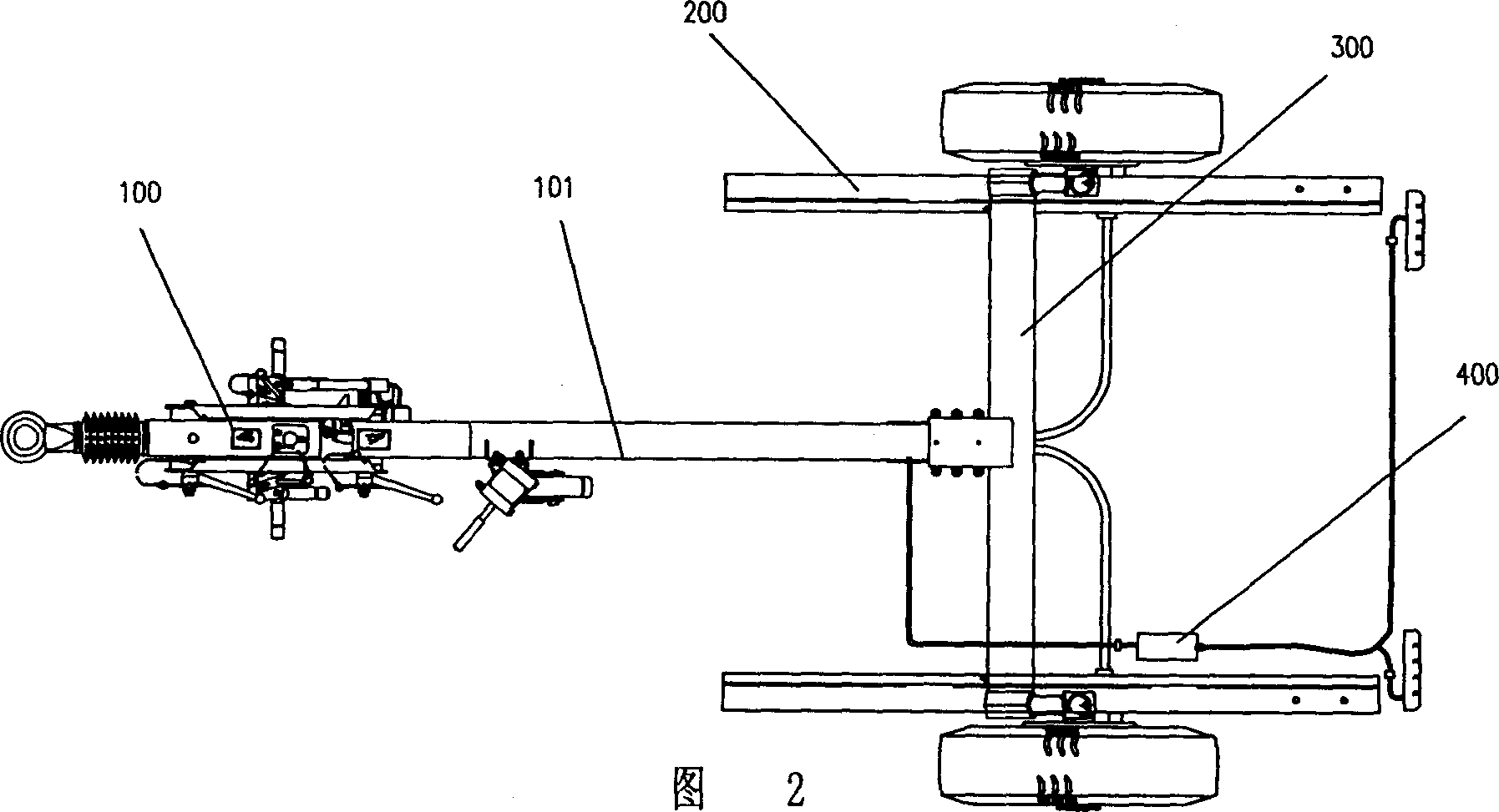
[0025] As shown in FIGS. 1 and 2 , the trailer of the present invention mainly includes a tractor head 100 , a subframe 200 , a suspension device 300 , a braking device 400 and a taillight system 500 .

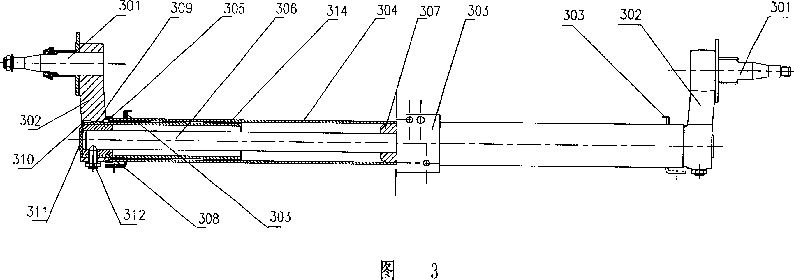
[0026]As shown in Figures 3 to 5, the suspension system 300 of the present invention includes two tire axles 301 arranged on both sides of the sub-frame 200, a balance arm 302 is respectively fixed on the two tire axles 301, and a balance arm 302 is respectively fixed at the bottom of the two balance arms 302. A hanging piercing hole is provided. A suspension beam 303 is fixed on the sub-frame, and the center of the suspension beam 303 is connected with the traction beam 101 of the traction head 100 through a connecting device 304 . A sealing and lubricating device 305 including a sealing ring is provided at the connection between the suspension beam...


PUM


Abstract

The trailer includes mainly one hauling machine, one auxiliary frame, one suspension device, one braking device and one tail lamp system. It features the suspension device with one nearly square torsion piece combination comprising elastic steel pieces; the braking device with one braking shoe assembly comprising one double layered rocker, two locating pins, one braking shoe plate and one braking friction sheet; the tail lamp system with at least one transition connector connected between one plug and one socket. The trailer has the advantages of capacity of being connected with different kinds of tractor, smooth running, etc.

Description

technical field [0001] The invention relates to a trailer. Background technique [0002] Trailers are widely used in vehicle transportation as an effective way to increase vehicle transportation. A general trailer is mainly composed of a tractor head, a sub-frame connected to the traction head, a suspension device, a brake device, a taillight system, and a trailer cabin, etc. composition. The existing trailers have the following problems: 1. Traditional trailers generally use leaf spring suspension as the trailer suspension device to connect the car body and wheels, which have a large volume, high center of gravity and poor stability; This problem can be better solved, but the general torsion shaft is a circular torsion bar, the torsion angle of the circular torsion bar is small, and the overall torsion bar has small elasticity and energy storage. 2. The inertia braking device of the existing trailer includes two brake shoe assemblies, one end of the two brake shoe assembl...

Claims


Application Information

Patent Timeline
Patent Type & Authority Applications(China)
IPC IPC(8): B62D63/06B60G11/20B60D1/64B60Q1/26F16D51/10
Inventor 姜聚华刘勇王铁卓宋福洋
Owner 北京军适机械有限公司
Why Eureka
Try Eureka