Internal combustion engine with a lubricating, cooling and starting system

A technology of lubricating system and cooling system, applied in the field of internal combustion engine, can solve the problems of prolonged assembly time, troublesome pre-installation, etc.

Inactive Publication Date: 2007-06-06
MAN ENERGY SOLUTIONS SA
View PDF0 Cites 3 Cited by
  • Summary
  • Abstract
  • Description
  • Claims
  • Application Information

AI Technical Summary

Problems solved by technology

[0007] The three individual components mentioned above require complex pre-assembly and thus greatly extend the final assembly time

Method used


Image

  • Internal combustion engine with a lubricating, cooling and starting system
  • Internal combustion engine with a lubricating, cooling and starting system
  • Internal combustion engine with a lubricating, cooling and starting system

Examples


Embodiment Construction

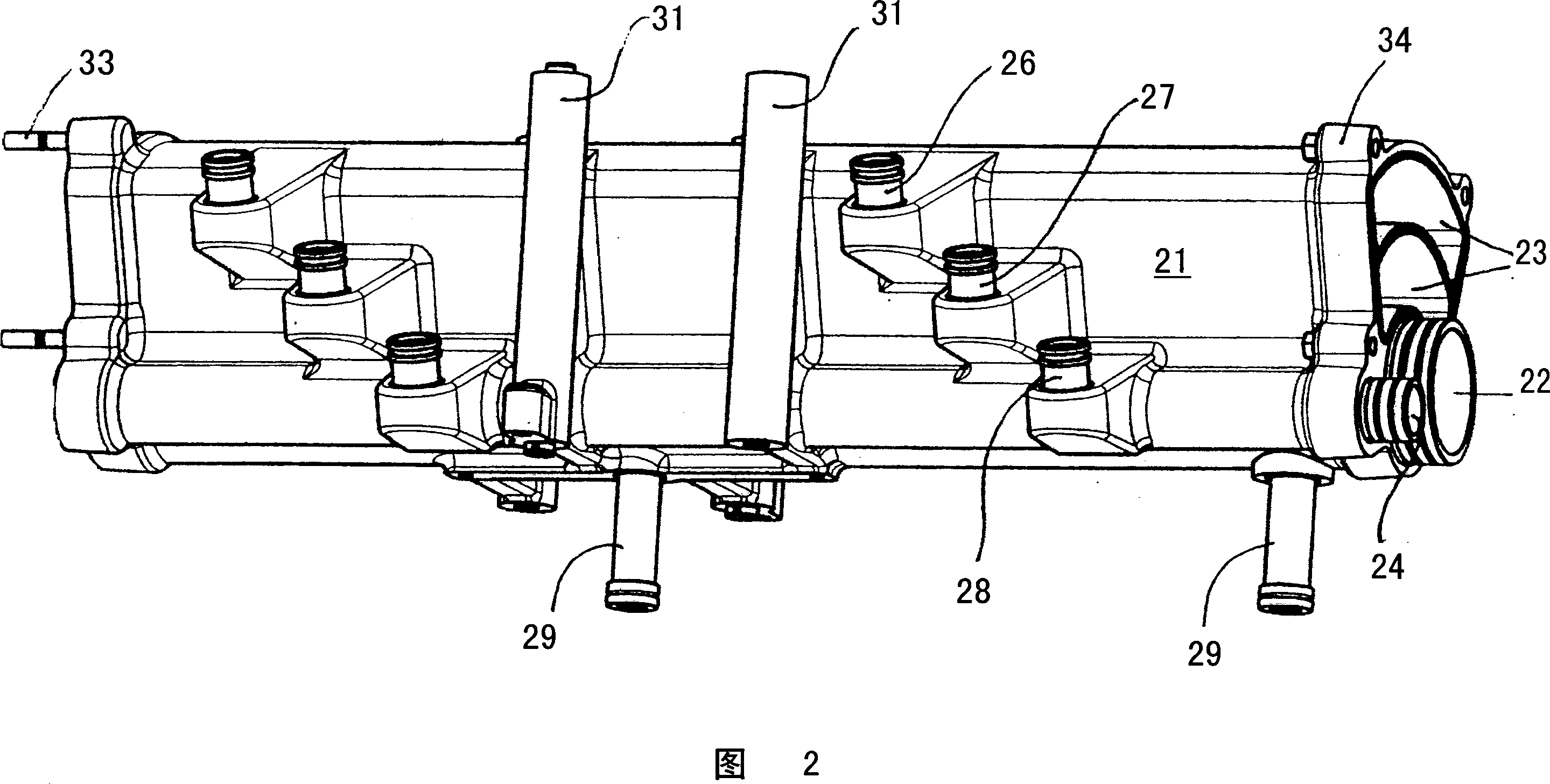
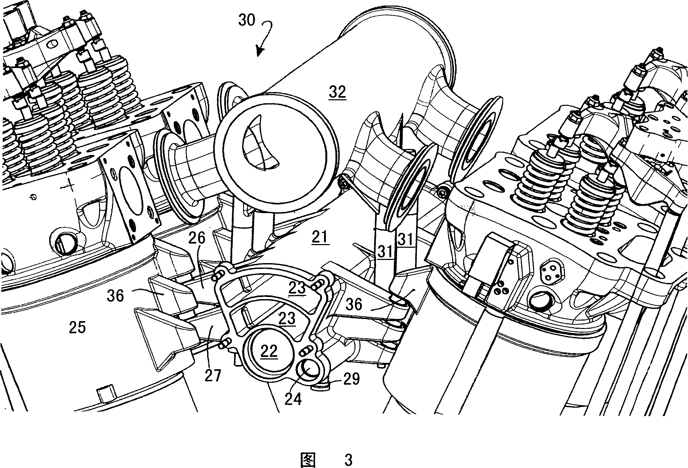
[0020] Corresponding parts are identified with the same reference numerals in FIGS. 2 and 3 .

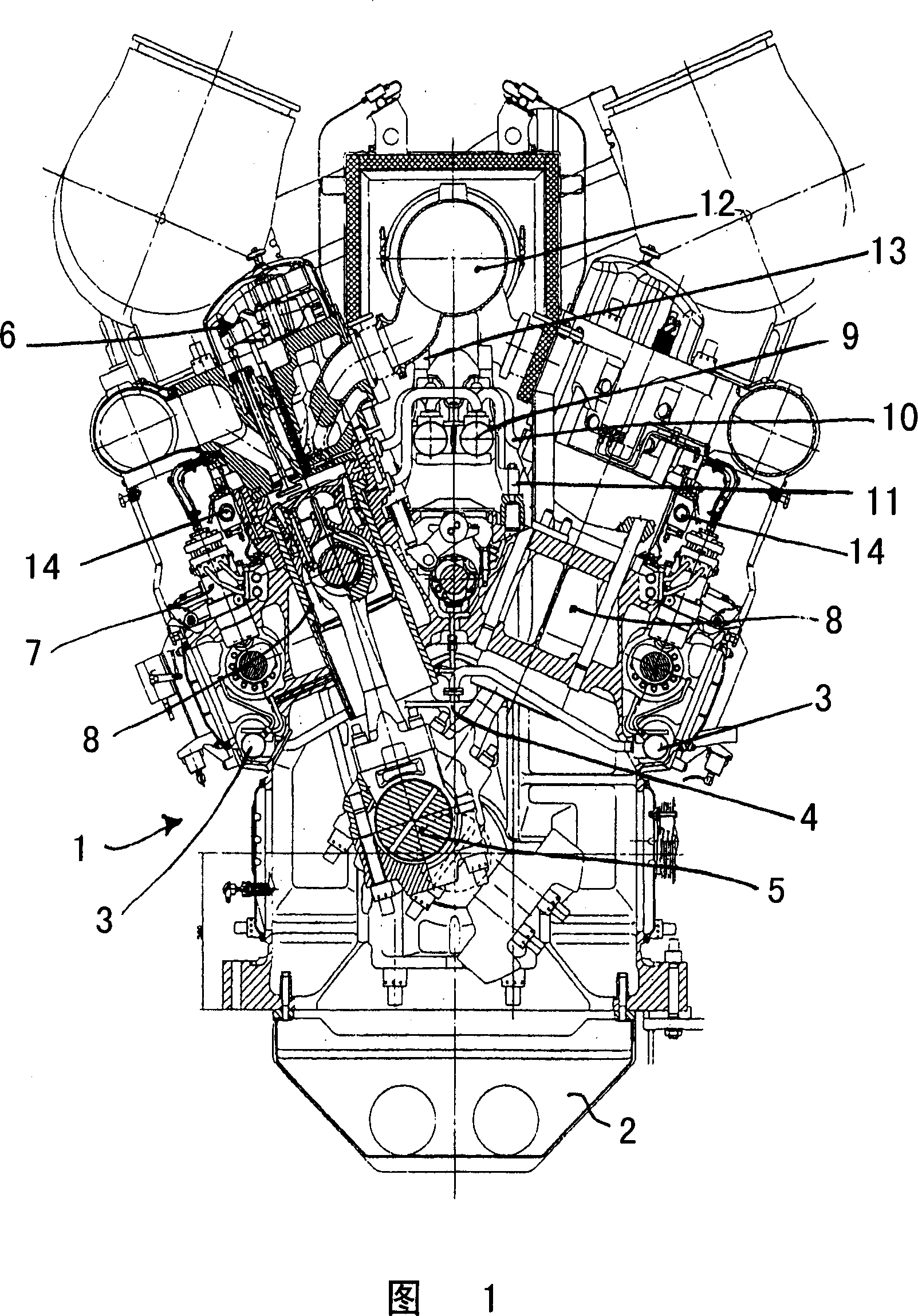
[0021] FIG. 1 shows a V-shaped engine, wherein the engine block 1 has an oil sump 2 in the lower part. Lubricating oil distribution lines 3 are provided along both outer sides of the engine block 1 , from which branch lines 4 for oil supply to the crankshaft 5 lead off.

[0022] A lubricating oil pump, not shown here, delivers the oil from a reserve oil tank in a known manner into the distribution line 3, from which branch pipes 4 lead to each crankshaft bearing and to the oil perforations in the crankshaft 5. to the position to be lubricated.

[0023] In addition, oil flows from distribution line 3 to valve drive 6 and to the roller tappets of fuel injection pump 7 .

[0024] Between the cylinders 8 of the V-engine, the inflow and outflow are arranged in the form of distribution lines 9 of the cooling system. The branch 10 leads to the internal duct of the engine block 1 in orde...


PUM


Abstract

The invention relates to a method for supplying lubricant, coolant and air inlet for start-up capable of reducing the assembly cost. The distributing pipes of the lubricant system, cooling system and start-up system are assembled in a common structure unit which is constituted by a plurality of dusting sections 21 for forming lubricant ducting, cooling water ducting and air inlet ducting for start-up, and is arranged along the engine block so as to connect the internal engine pipeline corresponding to the lubricant system, cooling system and start-up system by means of the separate transmitting ducting 26 to 29.

Description

technical field [0001] The invention relates to an internal combustion engine according to the preamble of claim 1 . Background technique [0002] Components of the lubrication system for the oil circulation lubrication of the engine, in particular the cylinders and the fuel supply system, but also the possibly provided supercharging device, in hitherto known, in particular medium-speed, four-stroke heavy oil engines , the components of the cooling system for supplying cooling water to, in particular, a plurality of cylinders arranged in the engine block and the components of the starting system for starting the internal combustion engine with compressed air are carried out as separate elements in the form of separate line assemblies implement. [0003] The above-mentioned internal combustion engine comprises, for example, a lubricating oil pump with a lubricating oil distribution line connected thereto, said lubricating oil pump passing through an engine built-in piping an...

Claims


Application Information

Patent Timeline
Patent Type & Authority Applications(China)
IPC IPC(8): F01M11/02F01P11/04F02N9/04
CPCF01M5/00F02F7/0012F01M11/02F01P11/04F02N9/04F01M1/06F01P3/00F02B75/22
Inventor M·桑根
Owner MAN ENERGY SOLUTIONS SA
Why Eureka
Try Eureka