Electromagnetic coefficient tester for electromagnetic material and testing method thereof

A technology of magnetoelectric materials and testers, which is applied in the direction of magnetic performance measurement, current/voltage measurement, instruments, etc., can solve the problems of not being able to measure the continuous change curve of the magnetoelectric coefficient, taking a lot of time and manpower, and having no magnetoelectric coefficient. Achieve test standardization, reduce labor intensity, and save test time

Inactive Publication Date: 2010-05-19
TSINGHUA UNIV
View PDF0 Cites 0 Cited by
  • Summary
  • Abstract
  • Description
  • Claims
  • Application Information

AI Technical Summary

Problems solved by technology

[0004] The shortcomings of the current testing technology are: only the magnitude of the magnetoelectric coefficient is measured, and there is no phase of the magnetoelectric coefficient; the output voltage of the magnetoelectric material is affected by the capacitance of the lead wire and the tester, which is lower than the real value and needs to be corrected ;Manually record data and operate instruments, the measurement process takes a lot of time and manpower; cannot measure the continuous change curve of magnetoelectric coefficient with angle

Method used


Image

  • Electromagnetic coefficient tester for electromagnetic material and testing method thereof
  • Electromagnetic coefficient tester for electromagnetic material and testing method thereof
  • Electromagnetic coefficient tester for electromagnetic material and testing method thereof

Examples


Embodiment Construction

[0028] Principle of the present invention, structure and specific implementation will be further described below in conjunction with accompanying drawing:

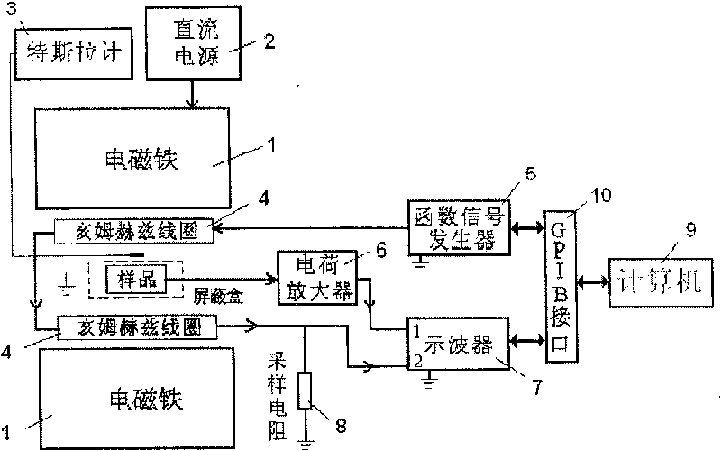
[0029] The circuit connection block diagram of the tester is as follows: figure 1 shown. The composition of the tester can be divided into the following parts:

[0030] (1) DC magnetic field generator

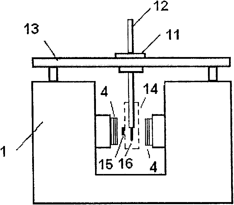
[0031] Including: electromagnet 1, DC power supply 2 and Tesla meter 3. The DC power supply drives the electromagnet to generate a DC bias magnetic field H DC . The probe 15 of the Teslameter is placed between the magnetic poles of the electromagnet for measuring H DC size and direction, such as figure 2 shown. Changing the output current of the DC power supply can change the H DC the size of.

[0032] (2) AC magnetic field generator

[0033] Including: Helmertz coil 4 and function signal generator 5. The function signal generator outputs a sinusoidal voltage with a frequency from 100Hz to 200kHz, driving the He...


PUM


Abstract

The invention relates to a test instrument and the test method for the magnetic electric coefficient of the magnetic electric material. The device includes the DC magnetic field generator, the AC magnetic field generator, the signal collecting device, the angle controlling device and the computer with the controlling software. The invention can not only detect the amplitude of the magnetic electric coefficient but the phase, so it is a perfect test system of the magnetic electric coefficient which includes the angle theta, HDC, HAC and frequency f. It can test the spectrum of the coefficient by the computer automatically and it saves the test time and decreases the work strength. The charge amplifier can cancel the influence of the lead capacitance. The angle controlling device can measurethe coefficient in region of 0degree-360degree.

Description

technical field [0001] The invention relates to an instrument and a testing method for measuring the magnetoelectric coefficient of a magnetoelectric material, belonging to the field of material performance testing. Background technique [0002] Magnetoelectric materials are materials with magnetoelectric effect. The magnetoelectric effect is a physical effect, with the magnetoelectric coefficient α E To measure the magnitude of the magnetoelectric effect, the unit is V / cmOe, that is, the electric field generated by the material per unit magnetic field. The magnetoelectric coefficient can be obtained by measuring the electric field generated by a magnetoelectric material under a known magnetic field. Magnetoelectric materials can be used in various functional devices such as magnetic field sensors, transducers, and transformers, and have attracted extensive attention from researchers. [0003] In 1981, Bracks et al disclosed a magnetoelectric coefficient testing device in...

Claims


Application Information

Patent Timeline
Patent Type & Authority Patents(China)
IPC IPC(8): G01R33/12G01R19/00G01R33/00G01R23/16
Inventor 施展南策文蔡宁翟俊宜马静
Owner TSINGHUA UNIV
Why Eureka
Try Eureka