Pipe network for connecting holed metal skeleton reinforced plastic composite pipe and plastic connector

A technology of plastic connectors and metal skeletons, which is applied in the direction of pipeline connection layout, pipes/pipe joints/fittings, pipes, etc., and can solve problems such as the difficulty of sealing skeletons

Inactive Publication Date: 2007-06-27
甘国工
View PDF0 Cites 3 Cited by
  • Summary
  • Abstract
  • Description
  • Claims
  • Application Information

AI Technical Summary

Problems solved by technology

There is a metal frame with holes for reinforcement, which is convenient for machines and tools to heat and socket pipes and pipe fittings. Especially when socketing, the outer plastic layer is the main welding layer. Due to the frame support, large-diameter pipes such as: larger than φ200 can be realized The hot-melt socket of the pipe, because the inner and outer plastic of the skeleton is a hot-melt body, it can thermally expand and slide between the inner and outer layers of the hole, and participate in the expansion and contraction of the hot-melt body. The pressure makes the hot-melt connection reliable. In addition, the end face of the pipe wall is inserted into the end face of the annular step in the inner cavity of the pipe fitting and fully heated and melted. Even more, the framework is completely covered and sealed by the molten body, which solves the difficult problem of the previous known technology that only relies on the plastic ring at the pipe end to seal the framework, and makes the pipe network of hot-melt socket connection more reliable than the known technology. The ability to withstand pressure and prevent corrosion of the skeleton, the more extension of the skeleton to the end face of the step, and the increase in the connection section of the end-face melt will all make the connection more reliable and withstand the more severe operating conditions of the pipe network, especially the plastic continuum of the pipe The difference in linear expansion between the thermal expansion and cold contraction and the order of magnitude between the skeleton has been overcome. Of course, the skeleton with holes here also plays a special role in restricting the linear expansion of the plastic continuum. This is also a plastic composite pipe with a metal skeleton with holes. The advantages and technical know-how of hot-melt connection with plastic pipe fittings to form a pipe network, because of such a combination and connection technology, the pipe network can be reliably applied to hot water pipe networks and pipe networks for hot corrosive fluids. A major breakthrough in technology

Method used


Image

  • Pipe network for connecting holed metal skeleton reinforced plastic composite pipe and plastic connector
  • Pipe network for connecting holed metal skeleton reinforced plastic composite pipe and plastic connector
  • Pipe network for connecting holed metal skeleton reinforced plastic composite pipe and plastic connector

Examples


Embodiment 1

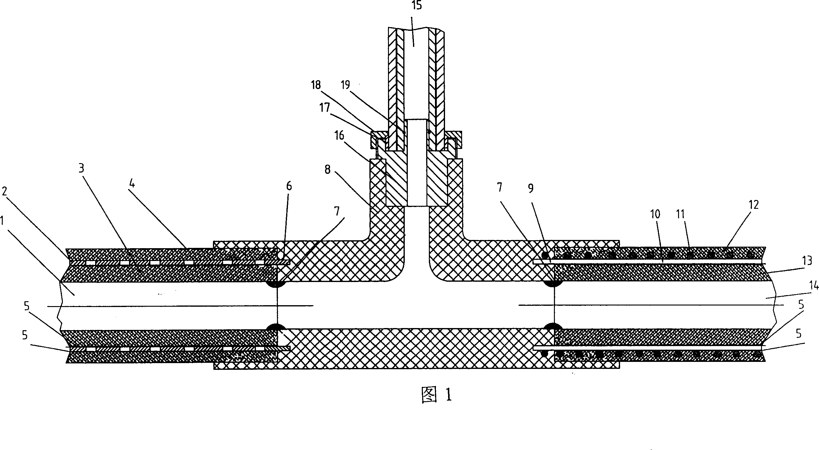
[0029] Fig. 1 has provided the figure of embodiment 1 of the present invention. Referring to Fig. 1, the steel-plastic composite pipe 1, the aluminum-plastic composite pipe 15, the latitudinal steel wire 11 and the radial steel wire 10 are welded into a composite pipe with a porous steel wire skeleton, which are connected by a three-way pipe connector 8 14 formed pipe network. The material of the plastic outer layer 4 in the steel-plastic pipe compounded with perforated steel strips is non-crosslinked heat-resistant polyethylene (PE-RT), which is melted and connected with the pipe connector 8, and the metal skeleton formed by butt welding of the perforated steel strips Part of the metal skeleton 6 exposed at one end of 2 extends into the end face 7 of the ring-shaped step in the inner cavity of the socket of the pipe fitting 8 by 4 mm, and is a plastic melt that is melted and connected together by the end face of the wall of the composite pipe 1 and the end face 7 of the ring-...

Embodiment 2

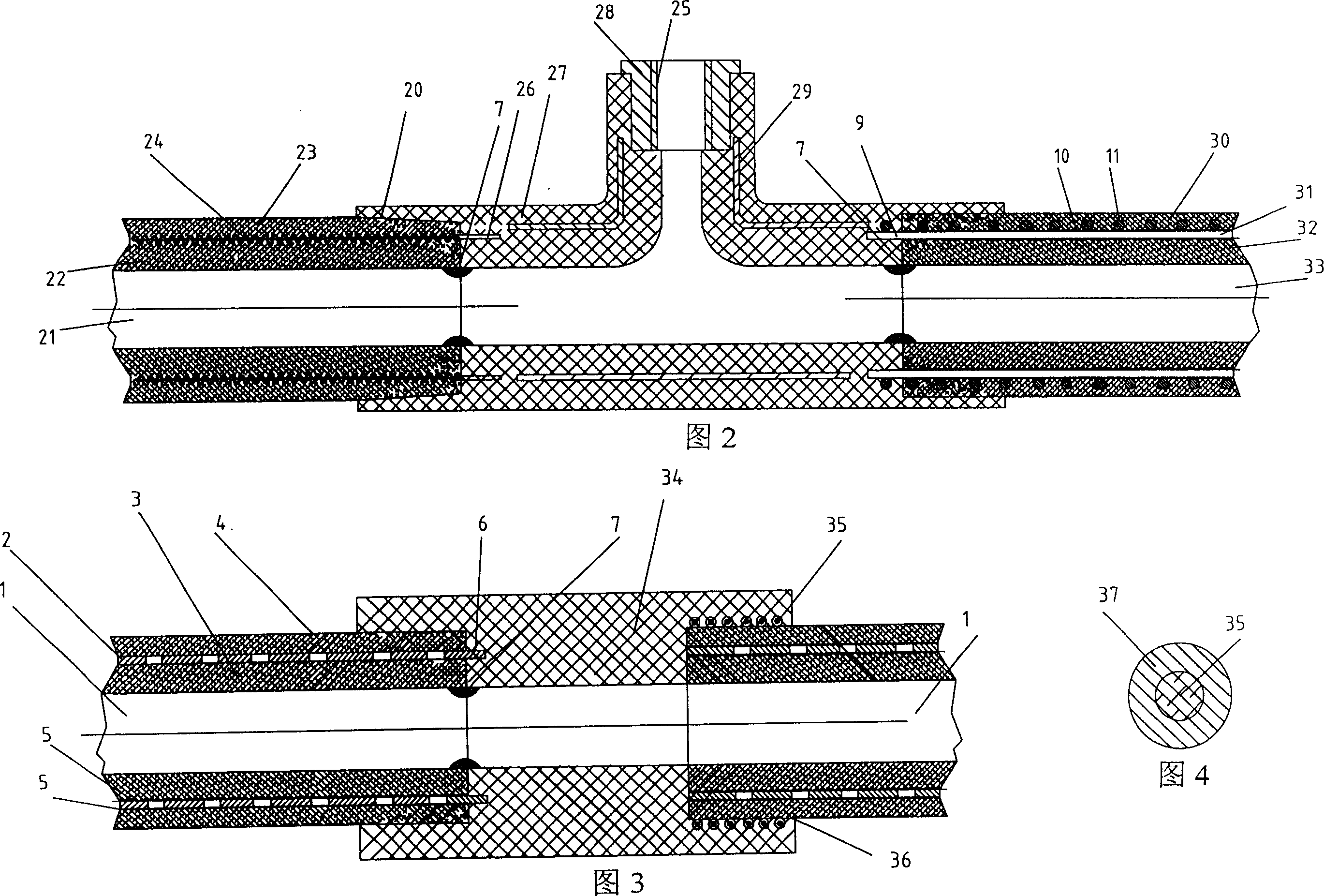
[0033] Fig. 2 has provided the figure of embodiment 2 of the present invention. Embodiment 2 is basically the same as Embodiment 1. The difference is that the inner layer 22 and outer layer 23 of the pipe 21 are all made of heat-resistant polypropylene (PP-R) or high-density polyethylene (HDPE), the pipe fitting 27 is a tee, and there is a steel plate skeleton 29 in the middle of the pipe fitting body. The connection at one end of the small diameter is to use the copper insert 28 with thread 25, and the metal skeleton 31 of the composite pipe 33 at the right end of the pipe fitting is formed by winding the radial steel wire 10 with the latitudinal steel wire 11 and welding. The inner layer 32 and the outer layer 30 of the pipe 33 The materials are all heat-resistant polypropylene (PP-R) or high-density polyethylene (HDPE). The metal skeleton of the composite pipe at the other end is wound with steel wire 24 left and right helically to form a skeleton. The end face 7 of the an...

Embodiment 3

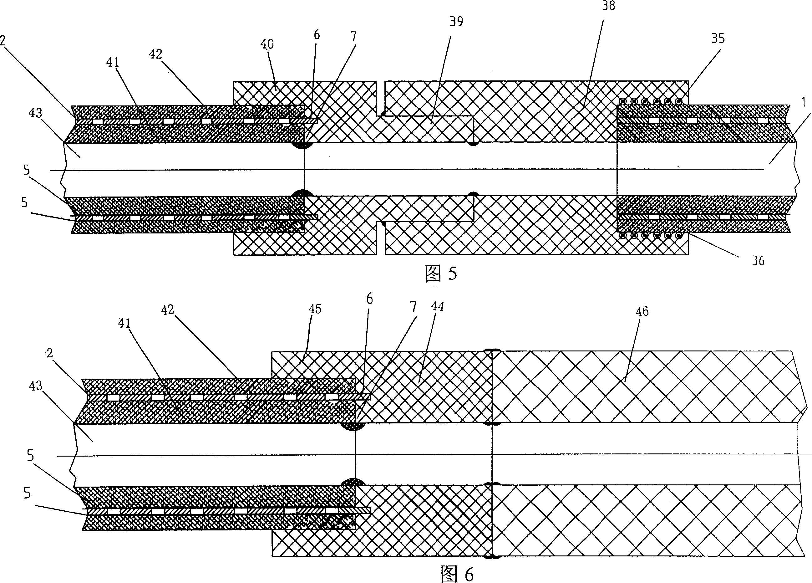
[0035] Fig. 3, Fig. 4 have provided embodiment 3 figure of the present invention. Embodiment 3 is basically the same as Embodiment 1. The difference is that the pipe fitting 34 made of non-cross-linked temperature-resistant polyethylene (PE-RT) is a two-way connection, one end is butt-welded with a perforated steel strip and a non-cross-linked temperature-resistant polyethylene compound with an adhesive layer 5 The end of the pipe 1 is hot-melt and socket connected, and the part of the metal skeleton 6 exposed at one end extends into the end face 7 of the annular step in the inner cavity of the socket of the pipe fitting 34. 7. The plastic melts that are melted and connected together are covered and sealed; the other end passes through the pipe fitting 34 and is directly inserted into the inner cavity 36 to distribute the heating wire 35 coated with the adhesive and the PE-RT blend 37 (see FIG. 4 ) and non-cross-linked heat-resistant polyethylene composite pipe 1 with a butt-...


PUM


Abstract

A tube network is composed of the perforated metallic skeleton reinforced composite plastic tubes and the plastic connecting tubes. Said composite plastic tube is formed by wrapping the perforated skeleton by plastics and consists of skeleton, internal plastic layer and external plastic layer. Said plastic connecting tube has at least one stepped socket end for connecting one end of said composite plastic tube by thermal fusion.

Description

Technical field: [0001] The invention is related to the connection of plastic pipes, steel-plastic composite pipes and plastic pipe fittings, especially the connection technology for connecting plastic composite pipes and plastic pipe fittings reinforced by metal skeletons with holes to form a pipe network through thermal fusion. Background technique: [0002] The connection between the known metal-composite plastic pipes and plastic pipes is connected by mechanical clamping method, and the electric heating wire distributed in the inner cavity of the socket of the pipe fitting is used. Fusion connection, there is a method of using hot-melt socket fusion connection between pure plastic pipes and plastic pipe fittings, but most of them are connected with small diameters, such as: pure plastic pipes less than φ110, and there are also unpublished methods that the author has applied for. The method of friction heat fusion connection, the method of heat melting the conical surface...

Claims


Application Information

Patent Timeline
Patent Type & Authority Applications(China)
IPC IPC(8): F16L9/147F16L47/02
Inventor 甘国工
Owner 甘国工
Why Eureka
Try Eureka