
On-line monitoring system method for overhead line by potential method

An overhead line and monitoring system technology, applied in the direction of electrical signal transmission system, signal transmission system, information technology support system, etc., can solve the problem of not being able to provide guidance for normal maintenance and troubleshooting of lines, and the monitoring and testing system cannot be well applied and promoted , unable to monitor the status of transmission lines, etc., to achieve the effect of being conducive to application and promotion, improving efficiency and cost performance, and low sensitivity

Inactive Publication Date: 2007-06-27
CHINA THREE GORGES UNIV +1
View PDF0 Cites 10 Cited by
  • Summary
  • Abstract
  • Description
  • Claims
  • Application Information

AI Technical Summary

Problems solved by technology

[0007] First of all, the detection content of these systems is relatively simple, and can only reflect individual problems or individual aspects of problems that occur during the operation of the line. For example, the remote online monitoring system for insulator leakage current only indirectly reflects the degree of contamination of insulators by detecting leakage current, and cannot affect power transmission. Comprehensive monitoring of the status of the line;
[0008] Secondly, these monitoring systems cannot identify and locate abnormalities (including faults); they cannot provide guidance for normal maintenance and troubleshooting of lines;
[0009] Thirdly, the cost of these detection systems is extremely high. With the addition of various sensors, front-end computers, power supplies, communication and other equipment, a tower must be equipped with detection equipment worth tens of thousands or even hundreds of thousands of yuan. These problems have led to the current Existing monitoring and measurement systems cannot be well applied and promoted

Method used


Image

  • On-line monitoring system method for overhead line by potential method

Examples


Embodiment Construction

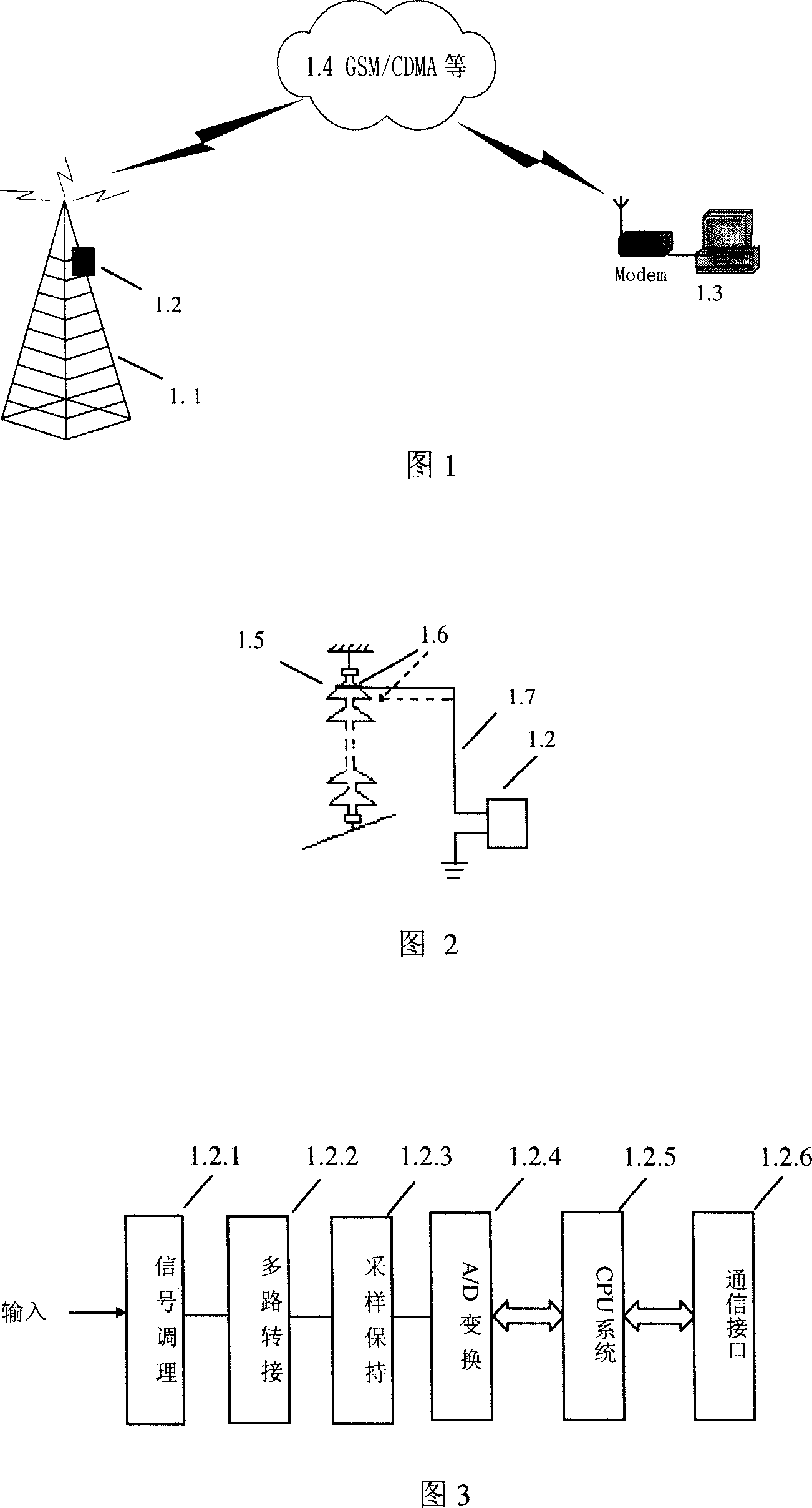
[0027] Fig. 1 is the connection relationship between the upper computer and the front-end computer of the present invention. It mainly consists of two parts: front-end computer 1.2 and upper computer 1.3. The front-end computer 1.2 is fixed on the horizontal tower material of the pole tower 1.1 nearby, and the front-end computer 1.2 and the host computer 1.3 are wirelessly connected through the GSM / CDMA network 1.4 for data transmission.

[0028] Figure 2 is the connection relationship between the front-end computer and the insulator string, 1.5 is the insulator, and 1.6 is the potential detector. The potential detector 1.6 can be fixed on the upper surface of the insulator 1.5 for direct electrical connection; it can also be fixed on the tower material near the insulator string to measure the induced potential at the fixed point. The front-end processor 1.2 and the potential detector 1.6 are directly electrically connected through a coaxial cable 1.7. The coaxial cable 1.7 ...


PUM


Abstract

Through monitoring change of electric potential at a fixed point on high voltage transmission tower in real time, the invention determines whether there is an abnormity (including fault) in high-tension overhead line as well as carries out abnormal recognition, state estimation, abnormal positioning, and abnormal alarm based on variation character of potential under each condition. The disclosed device is composed of electric potential detector, front-end processor (FEP), and up position device. Comuniation between FEP and the up position device is carried out through GSM / CDMA etc. wireless network. Through coaxial line, FEP is connected to the electric potential detector. Features are: high sensitivity, high ratio between performance and cost etc. Being related to all contents for daily operation, maintenance, inspection and repair for transmission line, the invention is able to implement entirety automation for transmission line not limited by weather and regions.

Description

technical field [0001] The invention relates to a detection method for power line faults, in particular to a transmission line real-time monitoring method and device using high-speed digital signal processing technology, wireless communication technology, pattern recognition technology, state estimation technology, abnormal recognition and fault location technology. Background technique [0002] Contamination, icing, flash welding, breakdown, bursting, and disconnection of insulators during operation must be discovered through inspections and inspections of power lines. Normal inspections are conducted once a month, and irregular night inspections are organized every year. [0003] Due to the large length and wide distribution of overhead lines, there are many chances of being struck by lightning, and there are many accidents caused thereby. In many areas, especially in the mountainous areas of Duolei, it is generally necessary to install a lightning positioning system, but ...

Claims


Application Information

Patent Timeline
Patent Type & Authority Applications(China)
IPC IPC(8): G01R31/08G01R31/00G01R31/02G01R19/00G01D21/00G01D21/02G08C17/02G08C19/00
CPCY04S10/522Y04S10/52
Inventor 王成江
Owner CHINA THREE GORGES UNIV
Learn More