Renovation technique of steam turbine rotor shaft fracture

A steam turbine rotor and process technology, which is applied in the direction of manufacturing tools, metal processing equipment, laser welding equipment, etc., can solve the problems of hidden dangers in the safe operation of the rotor, and the overall quality of the rotor shaft cannot be guaranteed 100%, achieving small thermal deformation and easy operation , strong normative effect

Inactive Publication Date: 2007-07-04
SHENYANG DALU LASER TECH
View PDF0 Cites 27 Cited by
  • Summary
  • Abstract
  • Description
  • Claims
  • Application Information

AI Technical Summary

Problems solved by technology

Affected by the specific connection method, machining accuracy and installation process, the overall quality of the roto

Method used


Image

  • Renovation technique of steam turbine rotor shaft fracture

Examples


Embodiment 1

[0013] Example 1 Restoration process for steam turbine rotor shaft fracture

[0014] The process steps are as follows:

[0015] 1. Failure cause analysis, providing basis for the design of new parts, connection methods and specific dimensions of interface parts:

[0016] 1.1 Metallographic analysis of damaged parts;

[0017] 1.2 Analysis of rotor material composition;

[0018] 1.3 Determine the cause of the rotor shaft fracture by analyzing the results.

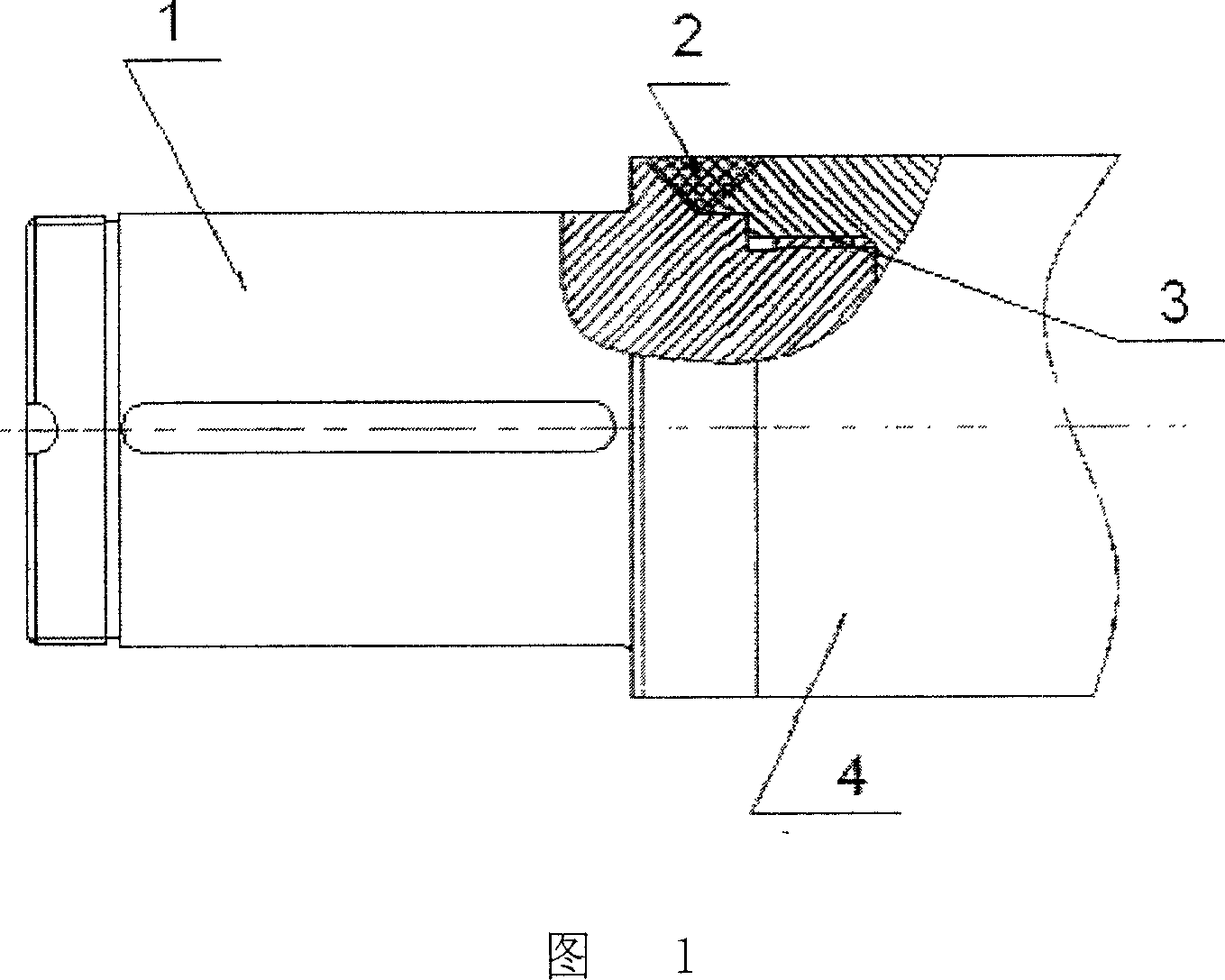
[0019] 2. Redesign a small part of the fracture

[0020] 2.1 Select the section with less stress as the location of the interface;

[0021] 2.2 According to the axial and radial loads borne by the rotor, it is decided to adopt the threaded connection plus laser cladding part method, and the core thread size and the laser cladding groove size are determined according to the load;

[0022] 2.3 Survey and map the dimensions of other parts of the fractured parts;

[0023] 2.4 Design according to surveying and mapping result...


PUM


Abstract

The invention discloses a restoring technique of cracked automobile wheel shaft, which comprises the following steps: manufacturing new piece; assembling and connecting new piece; manufacturing entire piece mechanically; proceeding lossless defectoscopic detection and dynamic balance of rotor; fusing to cover the mechanic connection and interface part through laser.

Description

technical field [0001] The invention relates to the maintenance and detection technology for the breakage of the steam turbine rotor shaft, and in particular provides a repairing process for the breakage of the steam turbine rotor shaft. Background technique [0002] The steam turbine rotor is a key component that converts the kinetic energy of the gas into mechanical energy. Steam turbine rotors are generally composed of rotor shafts, discs, blades and other parts. The steam turbine rotor shafts have high precision grades, complex manufacturing processes, high production costs, and long cycle times. The process conditions of the steam turbine rotor shaft are harsh, the working speed is from 3000 rpm to about 7000 rpm, the working temperature is 80-300 ℃, or even higher, and the service life of continuous operation must reach more than 20 years. [0003] The blank of the steam turbine rotor shaft is generally a high-quality alloy steel forging, which has strict quality requ...

Claims


Application Information

Patent Timeline
IPC IPC(8): B23P6/04B23K26/34
Inventor 刘豫陈江赵越
Owner SHENYANG DALU LASER TECH
Why Eureka
Try Eureka