Metal particles having intermetallic compound nano-composite structure crystal

a nano-composite structure and metal particle technology, applied in the direction of conductive layers on insulating supports, conductors, soldering apparatus, etc., can solve the problems of reducing mechanical strength, kirkendall void generation, and none of the conventionally known bonding materials have been sufficient to satisfy such requirements, and achieve high reliability, less likely to produce kirkendall, and high heat resistance

Active Publication Date: 2018-07-10
NAPRA
View PDF33 Cites 2 Cited by
  • Summary
  • Abstract
  • Description
  • Claims
  • Application Information

AI Technical Summary

Benefits of technology

[0013]It is therefore an object of this invention to provide a metal particle, an electro-conductive paste, and a formed article that are able to form a highly reliable and high-quality electric interconnect, an electro-conductive bonding portion, or a three-dimensional structure that is less likely to produce the Kirkendall void.
[0014]It is another object of this invention to provide a metal particle, an electro-conductive paste, and a formed article that are able to form a highly heat-resistant, highly reliable and high-quality electric interconnect, an electro-conductive bonding portion, or a three-dimensional structure.

Problems solved by technology

None of the conventionally known bonding materials has, however, been enough to satisfy such requirement.
Another problem inherent to the case where two or more semiconductor substrates are stacked and bonded, or the case where a three-dimensional structure is formed with a metal or alloy relates to reduced mechanical strength caused by Kirkendall void.
The Kirkendall void is generated when atomic vacancies (lattice defects), generated as a result unbalanced mutual diffusion of metals, accumulate rather than annihilate.
The Kirkendall void grows up to larger void or crack, may degrade reliability and quality of the bonding portion or the three-dimensional structure, may further reduce the mechanical strength, and can even result in separation, breakage, chipping or the like.

Method used


Image

  • Metal particles having intermetallic compound nano-composite structure crystal
  • Metal particles having intermetallic compound nano-composite structure crystal
  • Metal particles having intermetallic compound nano-composite structure crystal

Examples


Embodiment Construction

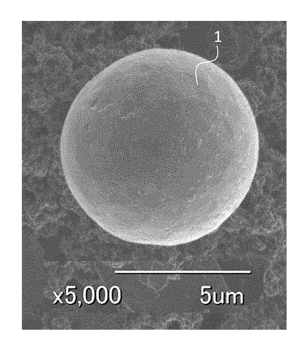
[0042]FIG. 1 shows an electron micrograph of a spherical metal particle 1 of this invention. The metal particle of this invention may be manufactured by a technique disclosed in JP-B2-4401281. The metal particle 1 is put into practical use in the form of powder, which is an aggregate of the particle.

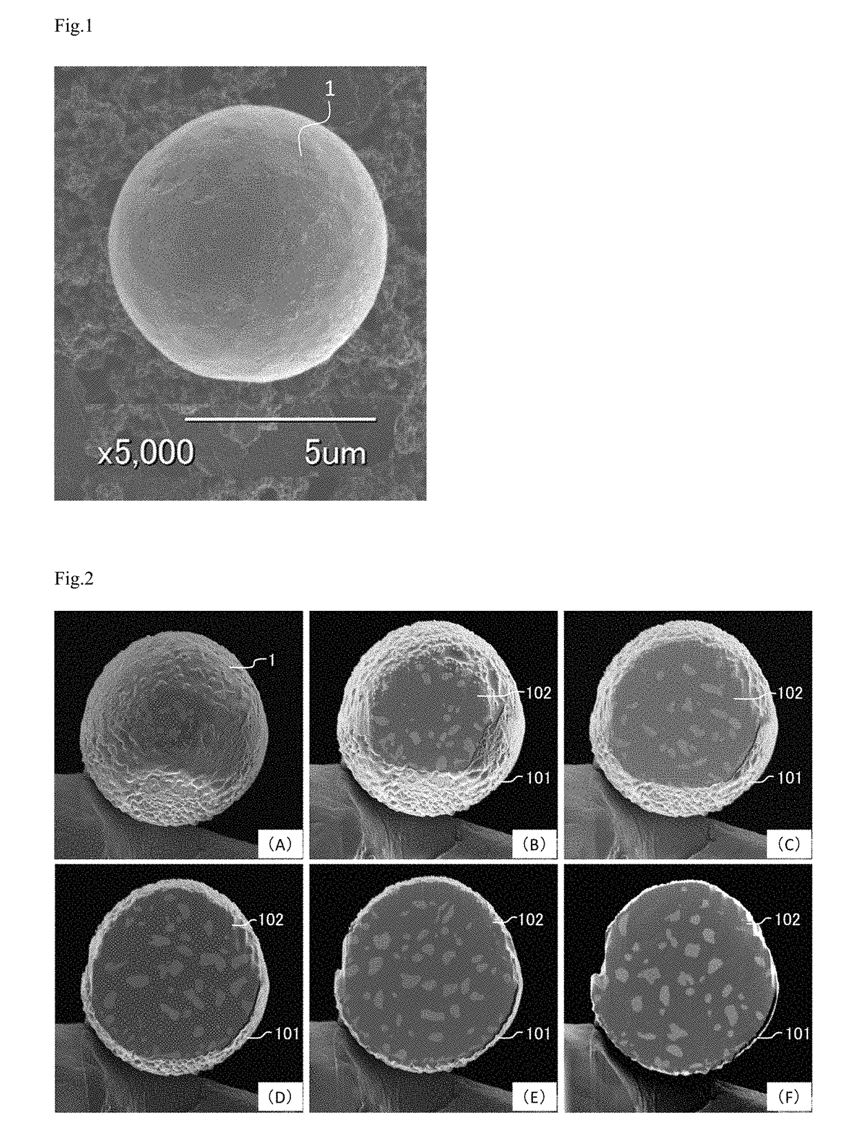
[0043]The metal particle 1 is composed of an outer shell and a core part, and the core part contains a metal, an alloy, or an intermetallic compound. The outer shell includes an intermetallic compound, and covers the core part. The detail will be explained, referring to a set of electron micrographs shown in FIG. 2. FIG. 2 is a set of electron micrographs showing cross-sections (A) to (F) of the metal particle 1 having a composition of 8% by mass of Cu and 92% by mass of Sn (referred to as 8Cu.92Sn hereinafter), wherein the cross-sections are taken by slicing it at regular depths from this side. FIG. 2(F) shows a cross-section taken so as to contain the diameter.

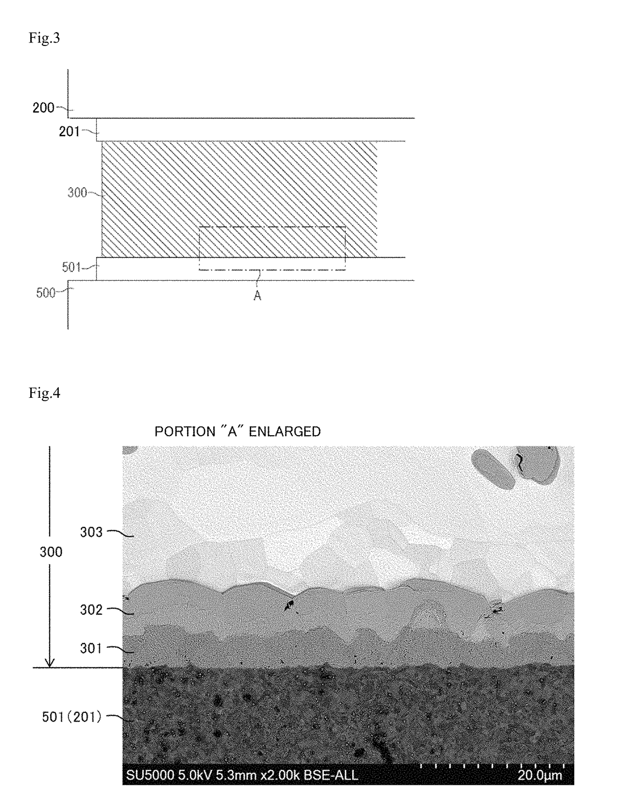
[0044]Referring now to FI...


PUM

PropertyMeasurementUnit
particle sizeaaaaaaaaaa
melting pointaaaaaaaaaa

Abstract

Aiming at providing a metal particle, an electro-conductive paste, a formed article, and a laminated article that are able to form a highly reliable and high-quality electric interconnect, an electro-conductive bonding portion, or a three-dimensional structure that is less likely to produce the Kirkendall void, this invention discloses a metal particle which include an outer shell and a core part, the outer shell including an intermetallic compound and covering the core part.

Description

CROSS-REFERENCE TO RELATED APPLICATIONS[0001]This application is based on the Japanese Patent Application No. 2016-065287, filed on Mar. 29, 2016, the entire content of which is incorporated hereinto by reference.FIELD OF THE INVENTION[0002]This invention relates to a metal particle, a paste, a formed article, and a laminated article.DESCRIPTION OF THE RELATED ART[0003]First, the terms used in this specification will be defined as follows:[0004](1) the term “metal”, “metal particle” or “metal component” is used for indicating not only a simple metal element, but also an alloy composed of two or more metal elements, a composite structure, or, a combination of them;[0005](2) “nanometer” denotes a range of dimension below 1 μm (1000 nm); and[0006](3) “metal matrix” denotes a metal or alloy that serves as a base material for filling up the gaps around, and supporting, other ingredients.DESCRIPTION OF THE RELATED ART[0007]In devices such as those kept operated at high temperatures for a ...

Claims


Application Information

Patent Timeline
Patent Type & Authority Patents(United States)
IPC IPC(8): B22F1/02B23K35/26B23K35/30C22C9/02H01L23/00C22C13/00H01B1/22B23K35/02B22F1/00B22F1/065B22F1/17
CPCB23K35/025B22F1/025B23K35/26B23K35/262B23K35/302C22C9/02C22C13/00H01B1/22H01L24/13H01L24/16B22F1/0048H01L2924/01327B22F2301/30B22F2301/40B22F2303/15B22F2303/30B22F2304/10H01L2224/13082H01L2224/13311H01L2224/13411H01L2224/13447H01B5/00H01B5/14B22F1/17B22F1/065H01B1/02H01B1/026H01B1/04B22F7/02B22F2301/10
Inventor SEKINE, SHIGENOBU
Owner NAPRA
Why Eureka
Try Eureka