
Combustion monitoring

a technology of combustion monitoring and combustion gas, which is applied in the direction of combustion types, lighting and heating apparatus, incinerator apparatus, etc., can solve the problems of undesirable release of pfcs into the environment, difficult removal of pfcs from effluent gas,

Active Publication Date: 2018-07-24
EDWARDS LTD
View PDF23 Cites 0 Cited by
  • Summary
  • Abstract
  • Description
  • Claims
  • Application Information

AI Technical Summary

Benefits of technology

The patent describes a method for monitoring the operation of a radiant burner using an infrared detector. The method is non-invasive, meaning it does not require direct interaction with the process gas stream. It is less likely to be affected by the deposition of effluent reaction products and is thus less likely to give false negative or positive signals, causing unnecessary shutdown of a combustion system. The method can also improve the recovery time of a system and provide a simple "off switch" in relation to a mode of operation of the radiant burner in which excess air is determined to be fed to the combustion chamber.

Problems solved by technology

PFCs are difficult to remove from the effluent gas and their release into the environment is undesirable because they are known to have relatively high greenhouse activity compared to carbon dioxide.

Method used


Image

  • Combustion monitoring
  • Combustion monitoring
  • Combustion monitoring

Examples


Embodiment Construction

Radiant Burner—General Configuration and Operation

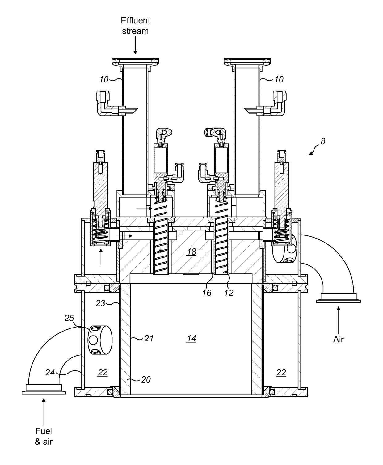
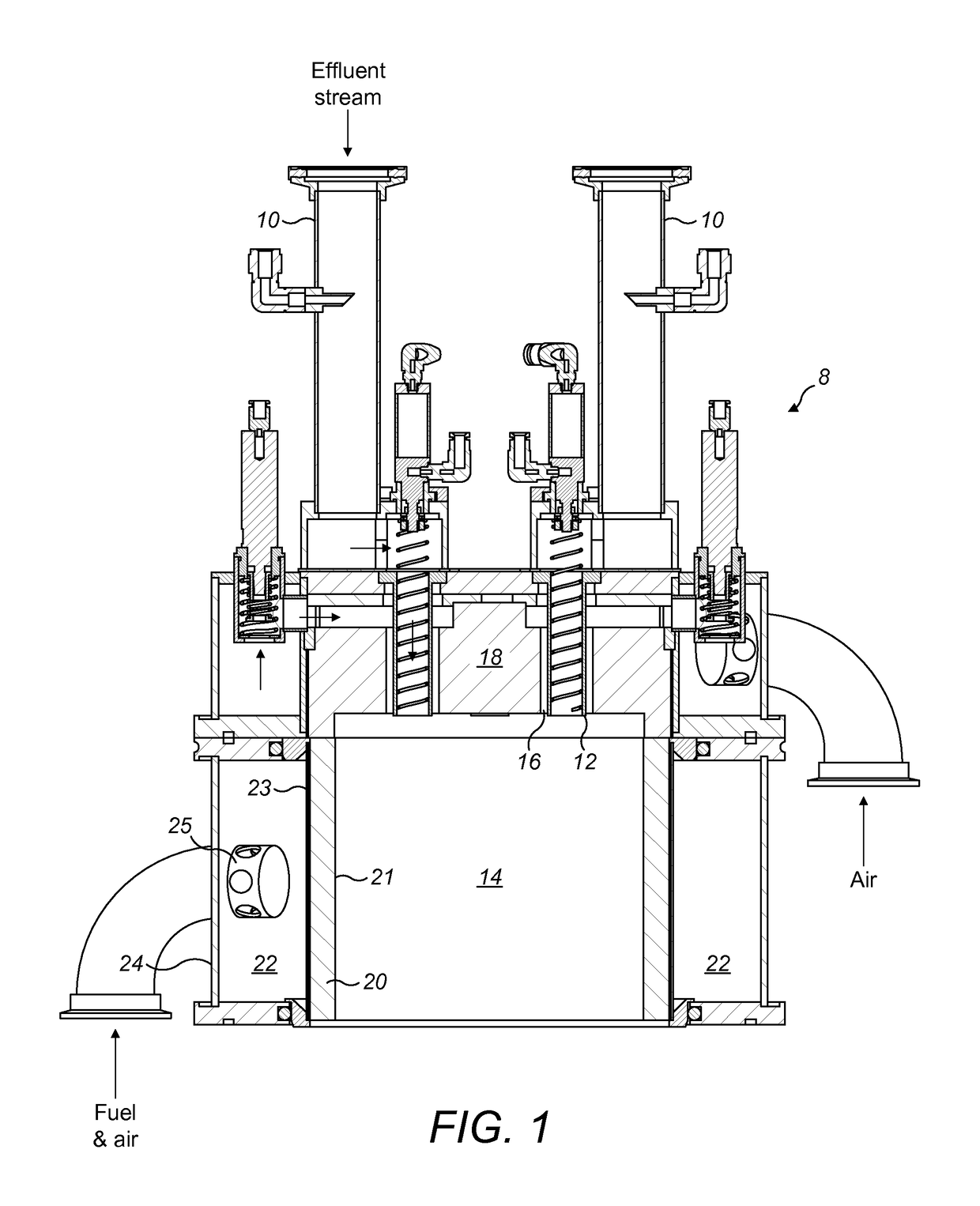
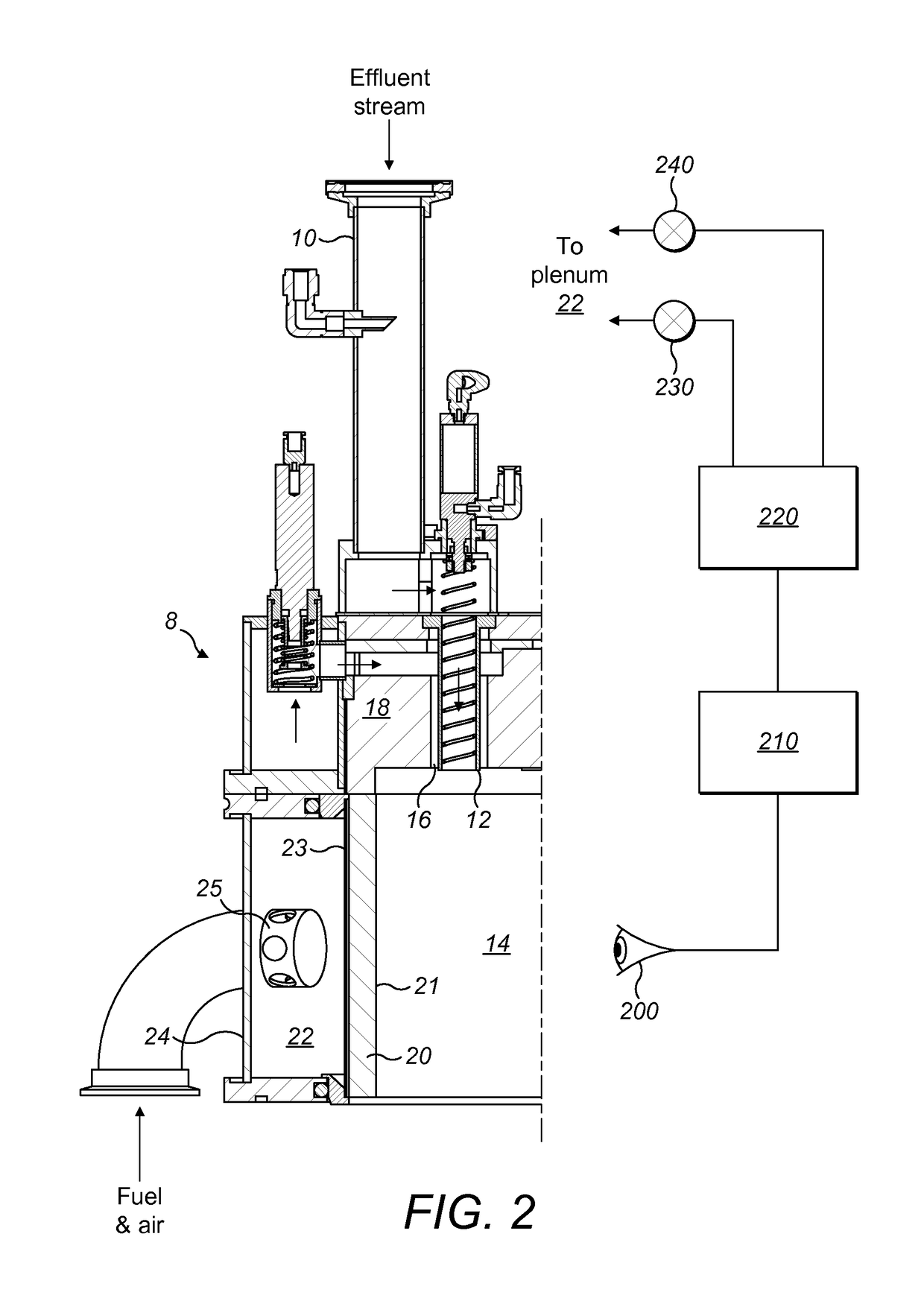
[0063]FIG. 1 illustrates a radiant burner, generally 8. The radiant burner 8 treats an effluent gas stream pumped from a manufacturing process tool such as a semiconductor or flat panel display process tool typically by means of a vacuum pumping system. The radiant burner shown in FIGS. 1 and 2 is of the type typically used to treat effluent gases from a chemical vapour deposition manufacturing process. The effluent stream is received at inlets 10. The effluent stream is conveyed from the inlet 10 to a nozzle 12 which injects the effluent stream into a cylindrical combustion chamber 14. In this embodiment, the radiant burner 8 comprises four inlets 10 arranged circumferentially, each conveying an effluent stream pumped from a respective tool by a respective vacuum pumping system. Alternatively, the effluent stream from a single process tool may be split into a plurality of streams, each one of which is conveyed to a respective inlet ...


PUM


Abstract

A radiant burner and method are disclosed. The radiant burner is for treating an effluent gas stream from a manufacturing process tool and comprises: a combustion chamber having a porous sleeve through which combustion materials pass for combustion proximate to a combustion surface of the porous sleeve; a combustion characteristic monitor operable to determine combustion performance of the radiant burner by monitoring infra-red radiation emitted from the combustion surface; and a radiant burner controller operable to control operation of the radiant burner in dependence upon combustion performance determined by the combustion characteristic monitor. Accordingly, aspects recognize that if a burner is suffering from an excessive flow of air the burner pad or combustion surface will typically cool, which results in an increase in unwanted emissions in the exhaust produced by a radiant burner. The cooling also results in a reduction in infrared radiation determined by the combustion surface. The hydrogen flame of the radiant burner and the hydrocarbon flame of the burner pilot typically do not emit infrared radiation and thus a change in infra-red an radiation, for example, intensity, quantity or frequency, emitted by the combustion surface of the radiant burner can be used to diagnose an “overflow” of cold gas, typically air, in the combustion mixture fed into the system, for example, the combustion chamber. Once diagnosed appropriate ameliorative steps may be taken and, for example, the burner control logic may be operable to compensate by reducing air flow into the burner.

Description

[0001]This application is a national stage entry under 35 U.S.C. § 371 of International Application No. PCT / GB2014 / 051188, filed Apr. 16, 2014, the entire content of which is incorporated herein by reference.TECHNICAL FIELD OF THE INVENTION[0002]The present invention relates to a radiant burner and method.BACKGROUND[0003]Radiant burners are known and are typically used for treating an effluent gas stream from a manufacturing process tool used in, for example, the semiconductor or flat panel display manufacturing industry. During such manufacturing, residual perfluorinated compounds (PFCs) and other compounds exist in the effluent gas stream pumped from the process tool. PFCs are difficult to remove from the effluent gas and their release into the environment is undesirable because they are known to have relatively high greenhouse activity compared to carbon dioxide.[0004]It will be appreciated that various semiconductor or flat panel display manufacturing no processes are utilised. ...

Claims


Application Information

Patent Timeline
Patent Type & Authority Patents(United States)
IPC IPC(8): F23D14/14F23D14/16F23G7/06F23C99/00F23N5/08F23N5/24F23N3/00
CPCF23N3/002F23C99/006F23D14/14F23D14/16F23G7/065F23N5/08F23N5/082F23N5/24F23N5/242F23G7/06F23G2209/142F23D14/126
Inventor STANTON, GARETH DAVIDPRICE, DUNCAN MICHAEL
Owner EDWARDS LTD
Learn More