High-power laser attenuator

a laser attenuator and high-power technology, applied in the field of lasers, can solve the problems of complex waterway connection, inconvenient installation and maintenance, difficult repair and short time, etc., and achieve the effect of simplifying the waterway connection and improving the safety protection level of the rotational structur

Active Publication Date: 2018-07-24
NANJING INST OF ADVANCED LASER TECH
View PDF3 Cites 0 Cited by
  • Summary
  • Abstract
  • Description
  • Claims
  • Application Information

AI Technical Summary

Benefits of technology

[0009]Preferably, the laser incident end of the lens barrel is sheathed with an indicating ring, and the adjusting rod is fixed on the indicating ring; and a scale ring with an empty slot in the middle is fixed on the surface of the housing, and the adjusting rod passes through the empty slot. Because the adjusting rod is restrained to move in the empty slot, the lens barrel can be forced to stopping rotation by obstructing the adjusting rod. The empty slot is matched with the adjusting rod to form mechanical limit preventing excessive adjustment of the attenuator.
[0018]The attenuator provided by instant examples alters the polarization direction of input laser by rotating the ½ wave plate to change the transmissivity of laser incident into the lens at the Brewster angle so that the purpose of energy attenuation of laser energy is achieved. The attenuator of the present invention simultaneously has an electric adjustment manner and a manual adjustment manner, and has photoelectric limit and mechanical limit for the adjustment of the attenuator, and the water swivels for water cooling heat dissipation of the absorber are arranged outside the attenuator housing which results electric and manual adjustment functions of the attenuator simultaneously, enhances the safety protection level of the rotational structure, and simplifies the waterway connection of the absorber, and the absorber can be connected into an external water cooling system conveniently and quickly, which is convenient for installation, replacement and maintenance of the absorber.

Problems solved by technology

In prior art, the attenuator is generally designed to only have a single adjustment manner, and once an adjustment device fails, it is difficult to repair and put into service within a short time.
In addition, it is also difficult for the single adjustment manner to meet the requirement of users for manual adjustment in some cases; during the adjustment process of the attenuator, the protective measures for excessive adjustment are relatively weak, and even are not considered, so that certain potential safety hazards exist; and for high-power laser, the absorber generally adopts water cooling heat dissipation, but the absorber is built into the attenuator in the existing design, so waterway connection is complex, and installation and maintenance are inconvenient.

Method used


Image

  • High-power laser attenuator
  • High-power laser attenuator
  • High-power laser attenuator

Examples


Embodiment Construction

[0023]The present invention will be further described in detail below in combination with the drawings.

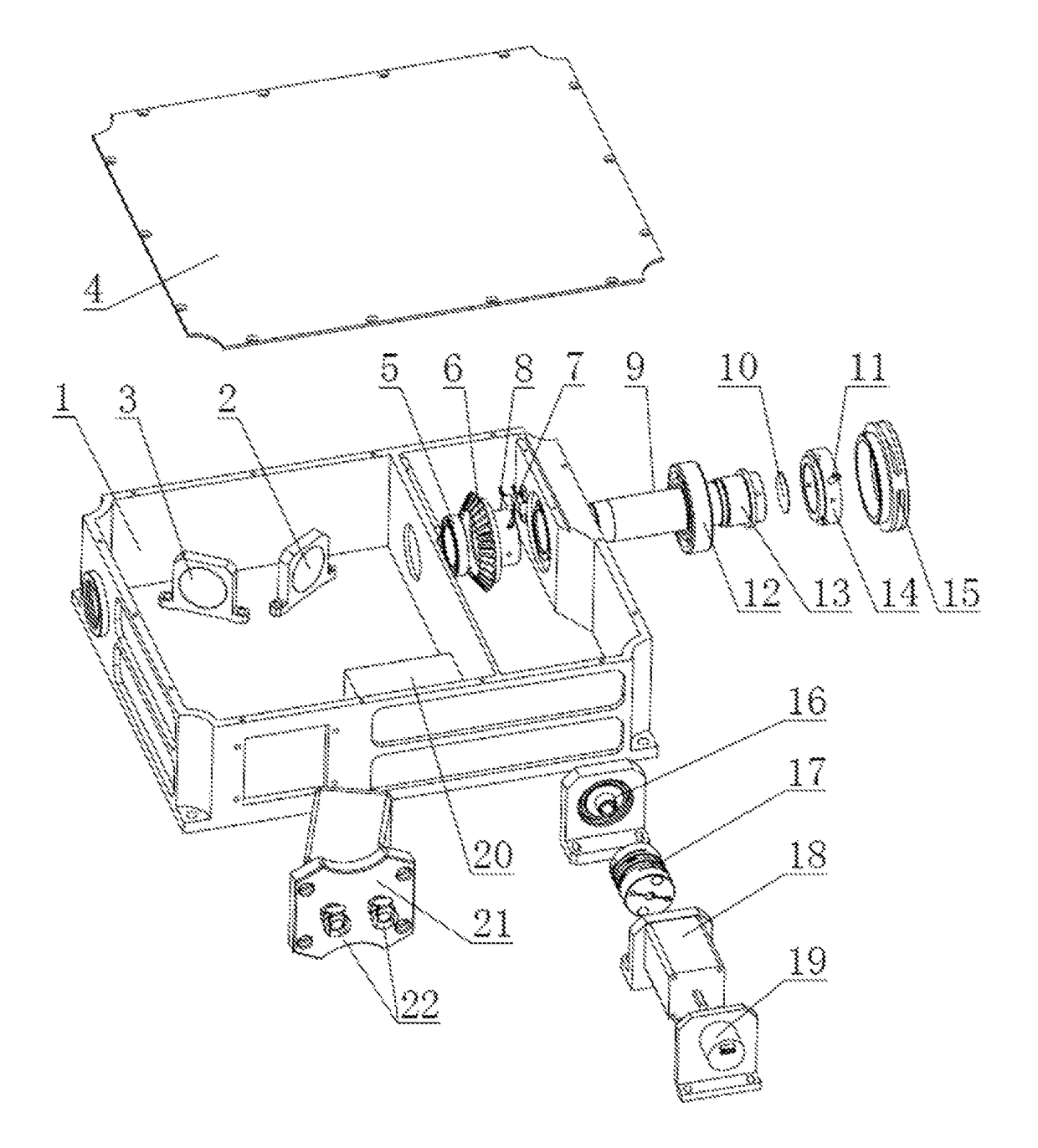
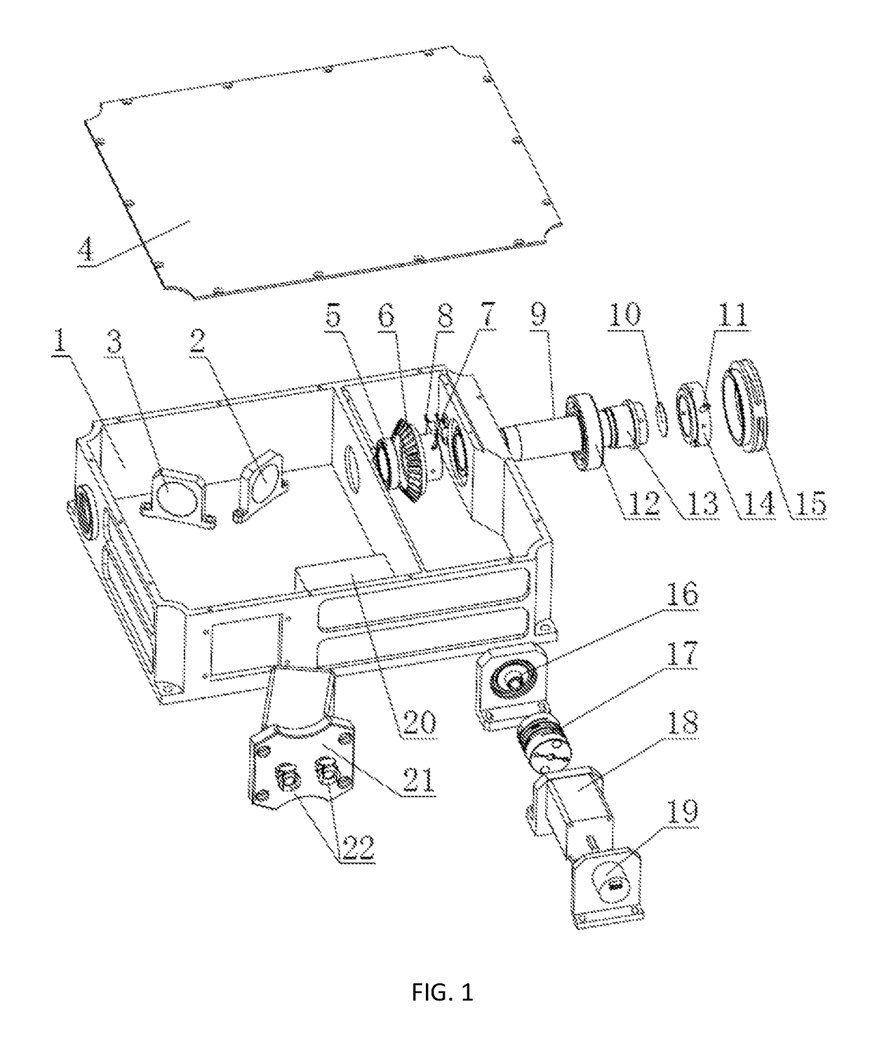
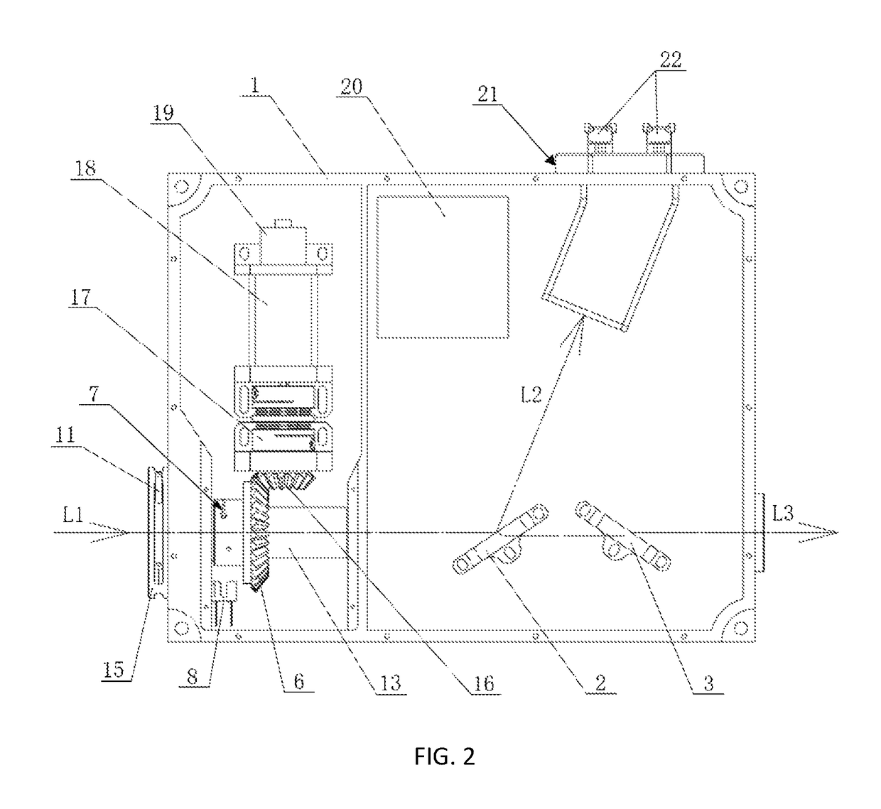
[0024]As shown in FIG. 1, the ½ wave plate 10, the first lens 2, the second lens 3 and the laser absorber assembly 21 which are placed in sequence on the incident light path of the attenuator along the laser incident direction form important nodes on the light path of the attenuator, and the integral structure that the upper cover 4 is removed after the whole attenuator is installed is shown in FIG. 2. Wherein:

[0025]The first lens 2 and the second lens 3 are perpendicularly arranged in mirror symmetry relative to the plane perpendicular to the incident light axis, and the normal lines of the incident mirror planes of the two lenses respectively form a Brewster angle with the incident light path; the ½ wave plate 10 is bonded to fixed to the lens barrel 13 near the laser incident end, and the indicating ring 14 is installed near the end of the ½ wave plate 10 in the lens barrel 13; ...


PUM

PropertyMeasurementUnit
intersection angleaaaaaaaaaa
poweraaaaaaaaaa
Brewster angleaaaaaaaaaa

Abstract

It relates to a high-power laser attenuator wherein laser is incident into an attenuator housing through a lens barrel; a ½ wave plate, a first lens and a second lens are arranged in sequence on an incident light path along a laser incident direction; the ½ wave plate can rotate around the incident light path, and normal lines of incident planes of the two lenses and the incident light axis are set to form a Brewster angle; a laser absorber assembly is arranged in a reflected light path of the first lens.

Description

[0001]This application claims priority to Chinese Patent Application Ser. No. CN201510955249.2 filed on Dec. 17, 2015.TECHNICAL FIELD[0002]The present invention belongs to the technical field of laser, and particularly relates to a laser power attenuation technology, in particular to an attenuator suitable for a laser of high power.BACKGROUND ART[0003]In a laser application system, laser power can be used or measured generally after attenuated by an attenuator. In prior art, the attenuator is generally designed to only have a single adjustment manner, and once an adjustment device fails, it is difficult to repair and put into service within a short time. In addition, it is also difficult for the single adjustment manner to meet the requirement of users for manual adjustment in some cases; during the adjustment process of the attenuator, the protective measures for excessive adjustment are relatively weak, and even are not considered, so that certain potential safety hazards exist; a...

Claims


Application Information

Patent Timeline
Patent Type & Authority Patents(United States)
IPC IPC(8): G02B27/28G02B5/00G02B5/30
CPCG02B27/281G02B27/283G02B5/3066G02B5/003G02B26/02H01S3/005B23K26/704
Inventor ZHOU, JUNLI, QIKUNXIAO, HUFUDING, JIANYONGDENG, CHENLI, ZHI
Owner NANJING INST OF ADVANCED LASER TECH
Why Eureka
Try Eureka