

Spark plug
a technology of spark plugs and spark plugs, which is applied in the manufacture of spark plugs, spark plugs, electrical equipment, etc., can solve the problems of partial wear (, “hollow”) of the melt portion, and wear of the intermediate member, so as to reduce the stress in the intermediate member, inhibit the growth of crystal grains, and inhibit the deformation of the intermediate member
- Summary
- Abstract
- Description
- Claims
- Application Information
AI Technical Summary
Benefits of technology
Problems solved by technology
Method used
Image

Examples
example 1
Production of Samples 1 to 38
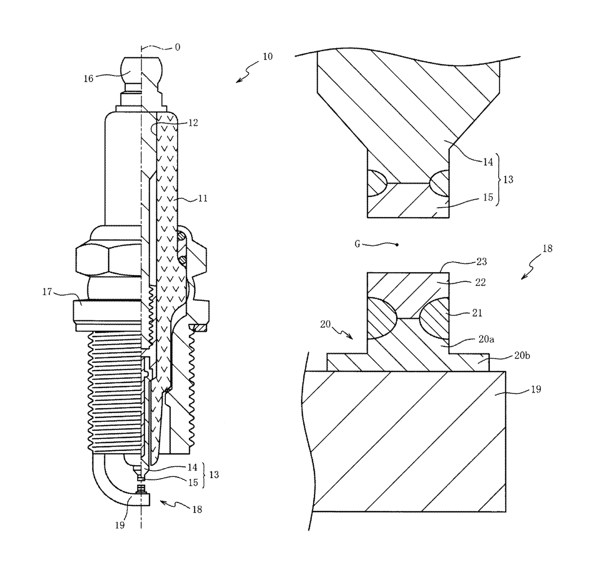
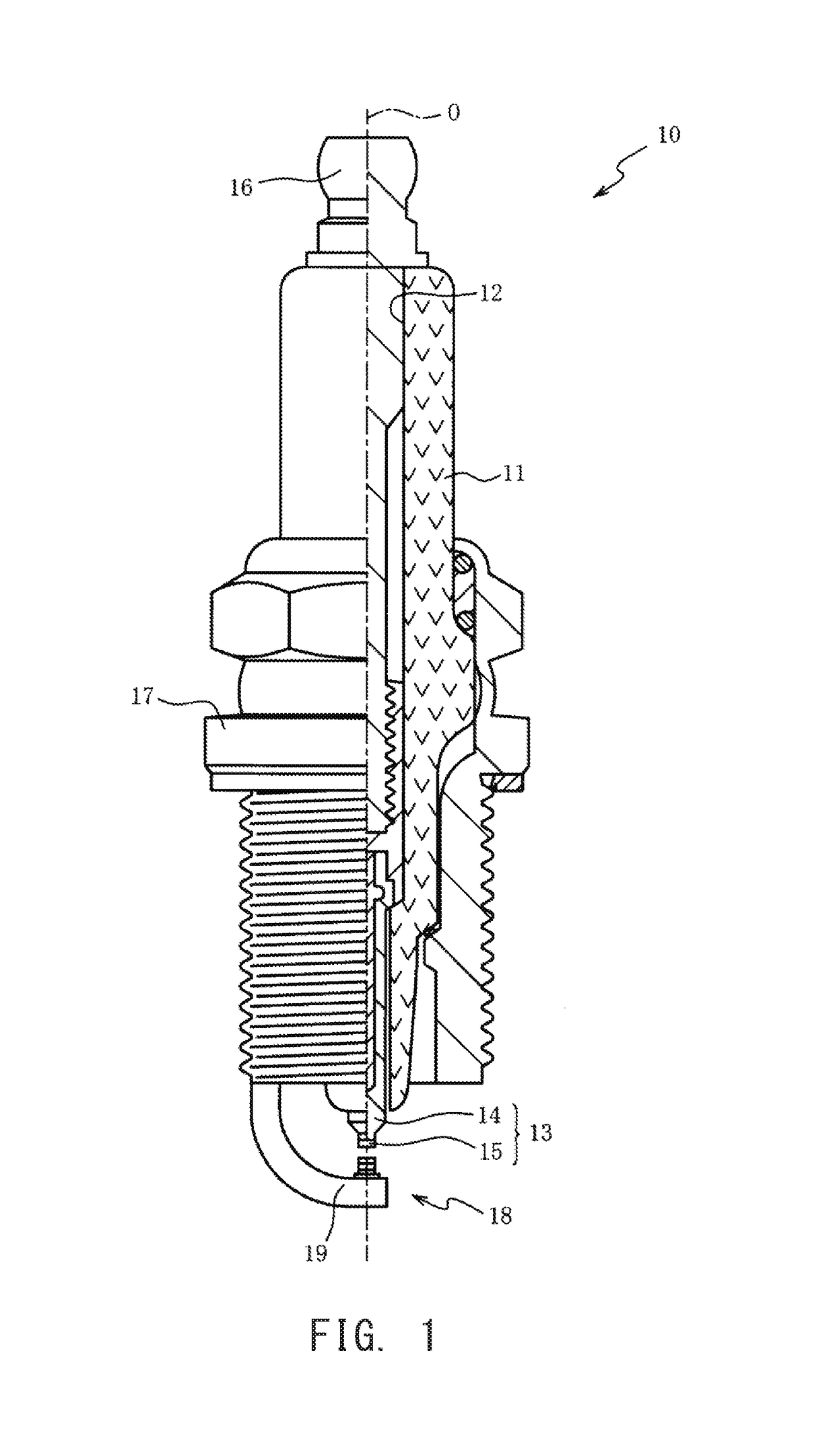
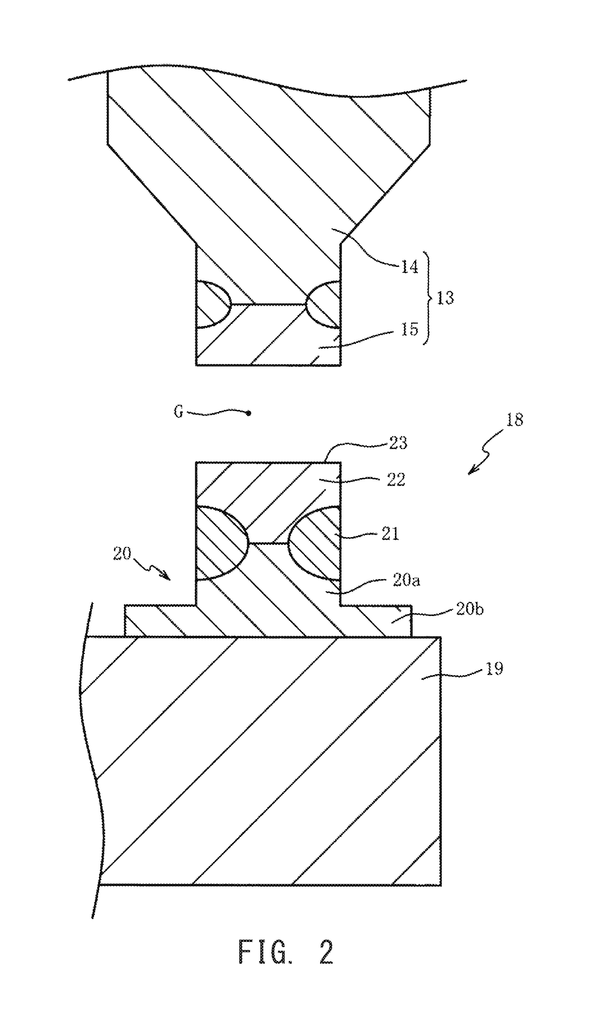
[0058]An examiner prepared: various cylindrical tips 22 having the same size and being composed of compositions shown in Table 1; and intermediate members 20 each including a column portion 20a of the same size and a flange portion 20b of the same size, and being composed of 75.0 wt % of Ni, 23.5 wt % of Cr, 0.5 wt % of Al, 1.0 wt % of Si, and inevitable impurities not more than a detection limit. After the end surfaces of each tip 22 and each intermediate member 20 were caused to abut against each other, laser beam was applied to the boundary between the tip 22 and the intermediate member 20 throughout the entire periphery by using a fiber laser welding machine. A melt portion 21 in which the abutting end faces were completely melted to disappear was formed between the tip 22 and the intermediate member 20, thereby joining the tip 22 and the intermediate member 20 together. The energy applied to the tip 22 and the intermediate member 20 by the fiber las...
example 2
Production of Samples 39 to 70
[0075]The examiner prepared: various cylindrical tips 22 having the same size and being composed of compositions shown in Table 2; and intermediate members 20 each including a column portion 20a of the same size and a flange portion 20b of the same size, and being composed of 75.0 wt % of Ni, 23.5 wt % of Cr, 0.5 wt % of Al, 1.0 wt % of Si, and inevitable impurities not more than a detection limit. In the same manner as in Example 1, spark plugs 10 corresponding to samples 39 to 70 were obtained.
[0076]
TABLE 2TipR groupN groupGrainPt(wt %)(wt %)OtherssizeNo.(wt %)RhIrRuNiCoFe(wt %)Pt + Rh + NiPt + R + NR / N(μM)Hb / HaCrack3980.020.0100.0100.0—1601.10NG4083.07.010.0100.0100.00.72.30B4183.07.010.0100.0100.00.72.25A4283.07.010.0100.0100.00.72.20A4383.07.010.0100.0100.00.72.15S4483.07.010.0100.0100.00.71.80S4583.07.010.0100.0100.00.71.50S4683.07.010.0100.0100.00.71.40S4783.07.010.0100.0100.00.71001.10S4883.07.010.0100.0100.00.71501.00S4983.07.010.0100.0100.00.7...
example 3
[0088]The examiner prepared: cylindrical tips 22 having the same size and being composed of 70 wt % of Pt, 20 wt % of Rh, 10 wt % of Ni, and inevitable impurities not more than a detection limit; and various intermediate members 20 being composed of compositions shown in Table 3, and each having a column portion 20a of the same size and a flange portion 20b of the same size. In the same manner as in Example 1, spark plugs 10 corresponding to the samples 71 to 78 were obtained.
[0089]
TABLE 3Intermediate memberWear of inter-No.NiCrFeAlSiYmediate member7186.510.02.51.0NG7248.132.017.01.81.00.1NG7375.023.50.51.0S7470.023.55.00.51.0S7565.923.59.00.51.00.1S7672.625.02.00.30.1S7781.515.02.51.0S7850.132.015.01.81.00.1S
[0090]In Table 3, the composition (mass %) of an alloy forming each intermediate member 20 is shown. Composition analysis for each intermediate member 20 was performed in the same manner as in Example 1.
Evaluation for Wear of Intermediate Member
[0091]After conducting the same d...
PUM
| Property | Measurement | Unit |
|---|---|---|
| crystal grain size | aaaaa | aaaaa |
| mass % | aaaaa | aaaaa |
| mass % | aaaaa | aaaaa |
Abstract
Description
Claims
Application Information