Rotating gas turbine blade and gas turbine with such a blade

a technology of rotating gas turbine blades and gas turbine blades, which is applied in the direction of blade accessories, engine components, machines/engines, etc., can solve the problems of insufficient use of centrifugal force to provide additional driving force, not using centrifugal force to pump the cooling medium, and negatively affecting the life of the blade. , to achieve the effect of increasing the guiding length

Active Publication Date: 2018-07-31
ANSALDO ENERGIA SWITZERLAND AG
View PDF6 Cites 1 Cited by
  • Summary
  • Abstract
  • Description
  • Claims
  • Application Information

AI Technical Summary

Benefits of technology

[0007]It is an object of the present invention to provide a rotating gas turbine blade, which is advantageous over the prior art blades, especially with regard to the degrading flow of cooling medium through the internal airfoil cooling passages.
[0016]Even more specifically, said guiding length is increased by inserting a tube into the machined opening and holding the tube in position by bonding, especially brazing or welding, and / or a mechanical interlock.

Problems solved by technology

However, the pumping work on the flowing cooling medium from centrifugal force is not or insufficiently used to provide additional driving force for the rotor 31 by ejecting the cooling medium against the blade's rotating direction.
However, dust present in the cooling medium or from the supply system may accumulate at the tip end and negatively affect cooling medium flow as well as add mass at the tip end, which may negatively affect the blade's life time.

Method used


Image

  • Rotating gas turbine blade and gas turbine with such a blade
  • Rotating gas turbine blade and gas turbine with such a blade
  • Rotating gas turbine blade and gas turbine with such a blade

Examples


Embodiment Construction

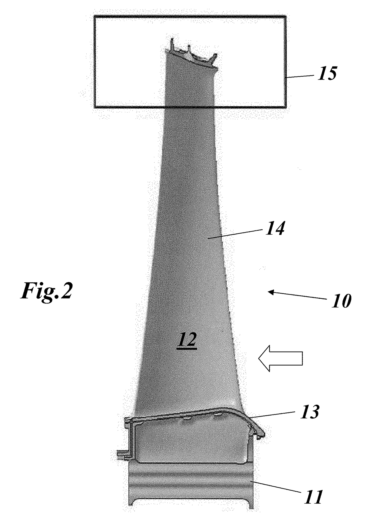
[0024]FIG. 2 shows in a side view a rotating gas turbine blade according to an embodiment of the invention. The turbine blade 10 of FIG. 2 comprises an airfoil 14, which extends in radial direction (with regard to the machine axis of the gas turbine) from a blade root 11 (with a fir tree configuration) to a shrouded blade tip 15. A platform 13 defines an inner wall of the annular hot gas channel between rotor 31 and casing 32. Airfoil 14 has a leading edge and a trailing edge (with regard to hot gas flow; see arrow in FIG. 2) as well as a suction side and a pressure side. The pressure side 12 is facing the viewer, in this case.

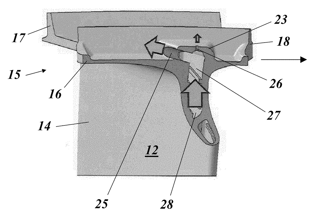
[0025]As can be seen in FIG. 3, blade tip 15 comprises a tip shroud 16, which is part of a partially closed or closed ring when all blades of the same turbine stage are mounted on rotor 31. Tip shroud 16 comprises on its upper (outer) side three parallel fins 17, 18 and 19, which extend along a circumferential direction. Neighbouring fins 17, 18 and 18, 19 def...


PUM


Abstract

A rotating gas turbine blade is disclosed which includes an airfoil with a suction side and a pressure side, the airfoil extending in a radial direction from a blade root to a blade tip. The blade tip includes a tip shroud, the airfoil having internal cooling passages for a cooling medium, which extend through the tip shroud. Outlet ports are provided above a selected internal airfoil cooling passage for the cooling medium to be ejected above the tip shroud in a direction of the blade's pressure side. Dust accumulation is avoided at the tip end of the selected internal cooling passage.

Description

BACKGROUND OF THE INVENTION[0001]The present invention relates to the technology of gas turbines. It refers to a rotating gas turbine blade according to the preamble of claim 1.[0002]It further refers to a gas turbine with such a rotating gas turbine blade.PRIOR ART[0003]FIG. 1 shows in a perspective, partially sectioned view an exemplary gas turbine with sequential combustion, which is known as type GT26 gas turbine. The gas turbine 30 of FIG. 1 comprises a rotor 31, which bears a plurality of rotating gas turbine blades with different functions and rotates around a central machine axis. The rotor 31 is enclosed by a casing 32. Gas turbine 30 has at one end an air inlet 33, through which air enters a compressor 34 to be compressed. The compressed air is used to burn a fuel and is used as a cooling medium for various parts of the gas turbine 30, which are exposed to high temperatures. As exemplary gas turbine 30 is designed as a reheat turbine with sequential combustion, there are t...

Claims


Application Information

Patent Timeline
Patent Type & Authority Patents(United States)
IPC IPC(8): F01D25/32F01D5/14F01D5/18F01D5/22
CPCF01D25/32F01D5/147F01D5/18F01D5/187F01D5/225F05D2260/607F05D2230/211F05D2240/305F05D2240/307F05D2260/20F05D2220/32
Inventor BALLIEL, MARTINGERSBACH, FRANKRETZKO, STEFAN ANDREASLAMMINGER, MARCO
Owner ANSALDO ENERGIA SWITZERLAND AG
Why Eureka
Try Eureka