
Thermal cycle continuous automated coal pyrolyzing furnace

a coal pyrolysis furnace, continuous technology, applied in the direction of vertical chamber coke ovens, coke quenching, discharging devices, etc., can solve the problems of low efficiency, no complete technique for exporting, purifying and utilizing raw gas, and continuous production, and achieve low efficiency and high labor costs

Inactive Publication Date: 2018-08-14
SHANXI XINLI ENERGY TECH
View PDF14 Cites 30 Cited by
  • Summary
  • Abstract
  • Description
  • Claims
  • Application Information

AI Technical Summary

Benefits of technology

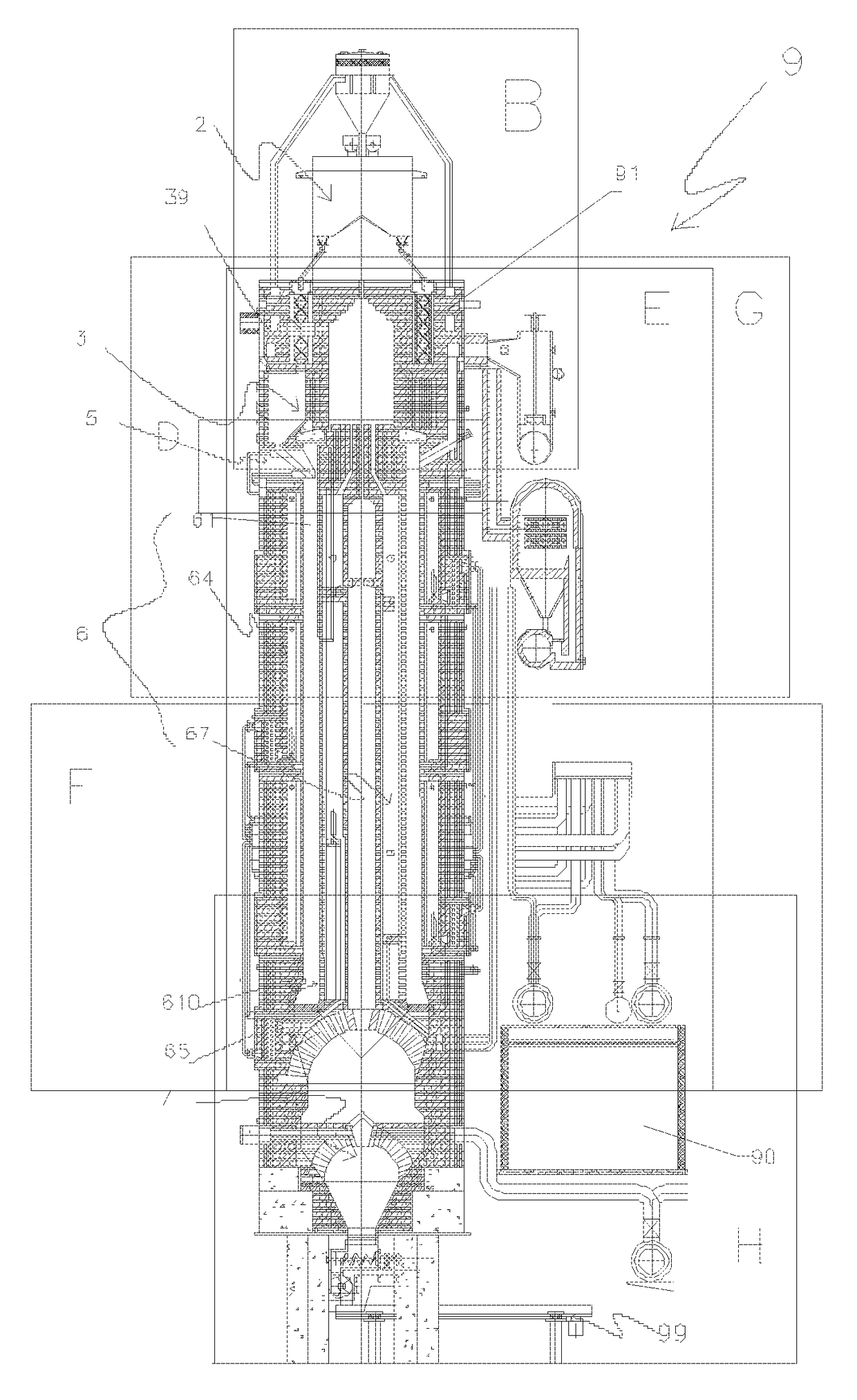
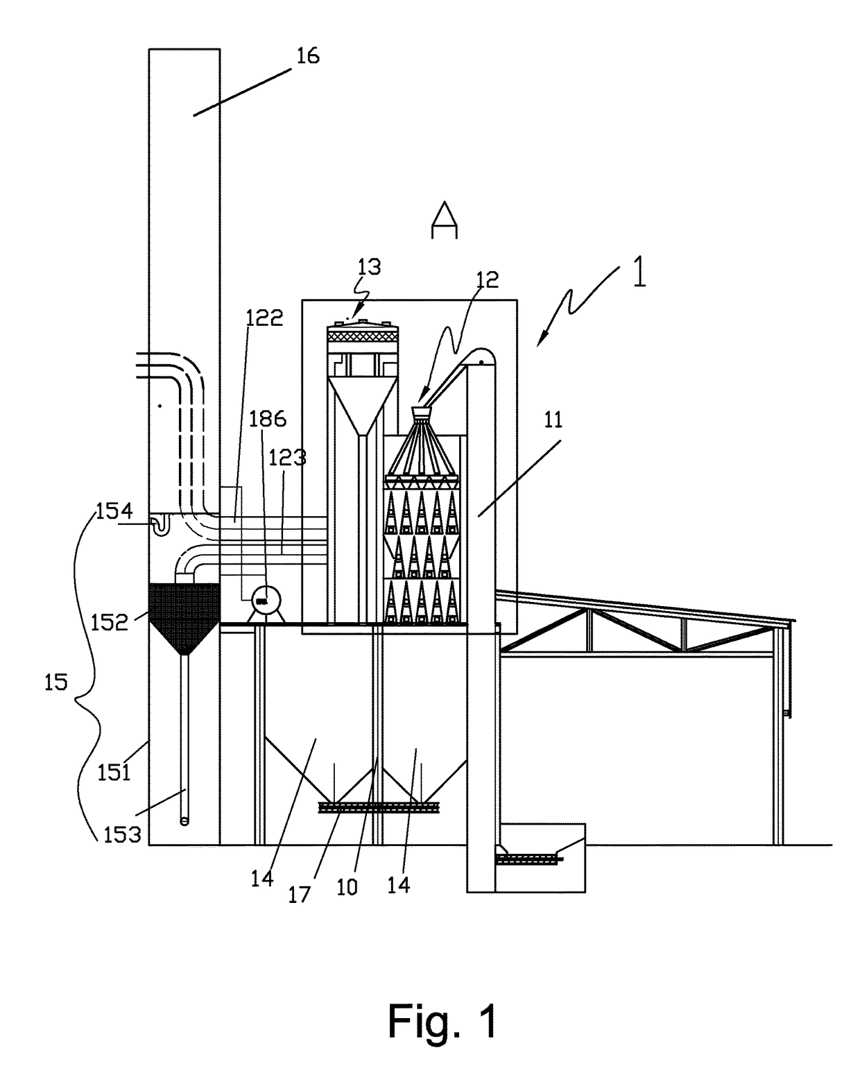
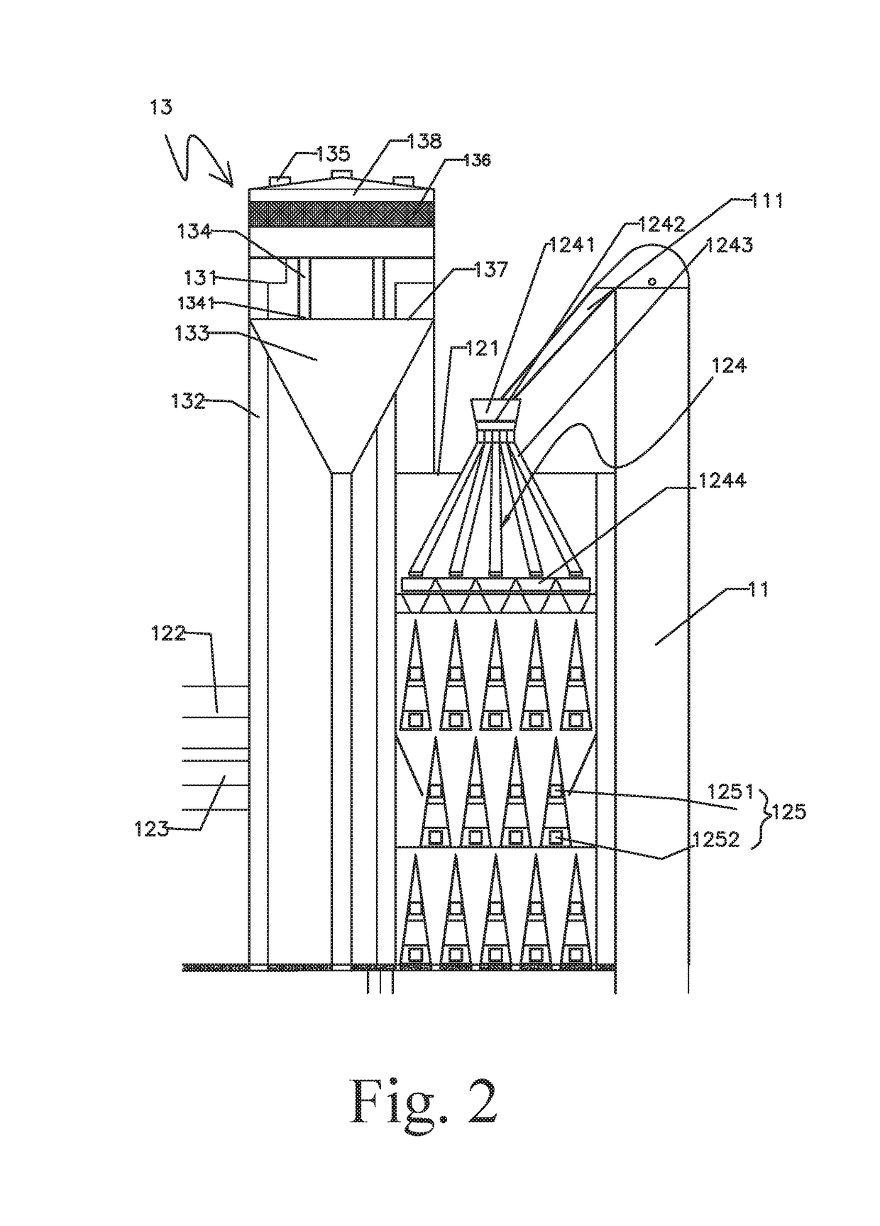
[0005]The present invention provides a thermal cycle continuous automated coal pyrolyzing furnace, which is capable of combining the coal feeding, pre-heating, coking, modification and dry quenching technologies into a whole for achieving the continuous coking, so as to improve the coking efficiency and reduce the coking cost.
[0061]The continuously quenching technologies of the present invention is capable of integrating coal inputting, preheating, coking, modification and dry quenching in one pyrolyzing furnace body, in such a manner that continuously quenching is achieved, which solves problems in the conventional intermittent coking technology of low efficiency, large plant areas for large amount of devices, high labor cost and etc.

Problems solved by technology

Conventionally, coal pyrolyzing furnaces (coke ovens) on the market usually utilize intermittent coking, wherein the proportion of inputting coal, dehydration, coal feeding, preheating, carbonization, coke modification, dry quenching, etc. are relatively independent, which results in discontinuous production and low productivity.
There is no complete technique for exporting, recovering, purifying and utilizing the raw gas.

Method used


Image

  • Thermal cycle continuous automated coal pyrolyzing furnace
  • Thermal cycle continuous automated coal pyrolyzing furnace
  • Thermal cycle continuous automated coal pyrolyzing furnace

Examples


Embodiment Construction

[0090]Preferred embodiments of a thermal cycle continuous automated coal pyrolyzing furnace of the present invention are illustrated as follows.

[0091]Part I: Proportion and Preparation of Inputting Coal

[0092]The coal pyrolyzing furnace, according to a preferred embodiment of the present invention, is capable of obtaining cokes of different levels according to different proportions of inputting coal.

[0093]The specific steps are as follows.

[0094]1) Five different kinds of coal are selected, which are gas coal, fat coal, coking coal, one-third coking coal and lean coal.

[0095]2) Weight percentages of the five kinds of coal are respectively 20%˜40% gas coal, 10%˜20% fat coal, 10%˜20% coking coal, 15%˜30% one-third coking coal and 10˜15% lean coal. The five different kinds of coal are mixed and then screened and crashed till a crashed particle size thereof is less than 5 mm for forming the inputting coal. Of course, other proportions and sizes of inputting coal are also adaptable to the c...


PUM

PropertyMeasurementUnit
particle sizeaaaaaaaaaa
temperatureaaaaaaaaaa
temperaturesaaaaaaaaaa

Abstract

A thermal cycle continuous automated coal pyrolyzing furnace, includes a furnace body, a coal feeding device, a preheating device, an inputting coal regulating bunker, an inputting coal cooling device, a coal pyrolyzation coking device, a coke modification device, a dry quenching device and a raw gas exporting device; wherein the coal feeding device, the pre-heating device, the inputting coal regulating bunker, the inputting coal cooling device, the coal pyrolyzation coking device, the coke modification device, the dry quenching device and the raw gas exporting device are all integrated on the furnace body; the coal pyrolyzation coking device includes a coking chamber, an external combustion gas heating device, an internal combustion gas heating device and a flame path bow. Utilizing the coal pyrolyzing furnace is capable of achieving continuously quenching, so as to improve quenching efficiency and decrease quenching cost.

Description

CROSS REFERENCE OF RELATED APPLICATION[0001]This is a U.S. National Stage under 35 U.S.C 371 of the International Application PCT / CN2013 / 080796, filed Aug. 5, 2013, which claims priority under 35 U.S.C. 119(a-d) to CN 201210279414.3, filed Aug. 6, 2012.BACKGROUND OF THE PRESENT INVENTIONField of Invention[0002]The present invention relates to a coal pyrolyzing furnace, and more particularly to a thermal cycle continuous automated coal pyrolyzing furnace.Description of Related Arts[0003]Conventionally, coal pyrolyzing furnaces (coke ovens) on the market usually utilize intermittent coking, wherein the proportion of inputting coal, dehydration, coal feeding, preheating, carbonization, coke modification, dry quenching, etc. are relatively independent, which results in discontinuous production and low productivity. In addition, raw gas produced during coal pyrolyzing comprises many useful ingredients, such as H2S, HCL acid gases, NH3 alkaline gas, tar, benzene, naphthalene, and absorber...

Claims


Application Information

Patent Timeline
Patent Type & Authority Patents(United States)
IPC IPC(8): C10B31/00C10B33/12C10B21/00C10B21/16C10B39/02C10B21/10C10B31/02C10B3/02C10B3/00
CPCC10B31/00C10B3/00C10B3/02C10B21/00C10B39/02C10B21/16C10B31/02C10B33/12C10B21/10
Inventor WANG, XINMIN
Owner SHANXI XINLI ENERGY TECH
Learn More