Solar generator with large reflector dishes and concentrator photovoltaic cells in flat arrays

a technology of solar generators and concentrators, applied in photovoltaics, electrical equipment, semiconductor devices, etc., can solve the problems of inability to convert by a single high-efficiency multi-junction cell placed at the focus, and inability to achieve unevenness, so as to prevent contamination

Active Publication Date: 2018-08-14
THE ARIZONA BOARD OF REGENTS ON BEHALF OF THE UNIV OF ARIZONA
View PDF127 Cites 1 Cited by
  • Summary
  • Abstract
  • Description
  • Claims
  • Application Information

AI Technical Summary

Benefits of technology

[0009]The present invention is an apparatus for generation of solar electricity by focusing sunlight onto small multi-junction photovoltaic cells having exceptionally high conversion efficiency. The invention addresses the key requirement for solar generation, namely low manufacturing cost and high overall efficiency. To this end, the apparatus includes a large paraboloidal mirror of back-silvered glass, turned to the sun throughout the day, so as to provide an intense focus. Solar reflectors of large back-silvered glass segments already used extensively to concentrate sunlight for solar thermal generation have been proven to have long life in field operation and are relatively inexpensive per unit of solar power brought to a focus. However, to exploit such large collectors in an economical system, it is necessary to inexpensively convert into electricity the powerful sunlight provided at the focus. The conversion cannot be accomplished by a single high-efficiency multi-junction cell placed at the focus, as is common for cells used with small lens collectors, because the electrical current would be so large as to cause a single cell to fail.
[0010]This invention provides for efficient operation of multi-junction photovoltaic cells at the powerful focus, by dividing the light to illuminate multiple small cells, each operating at a safe, reduced current. The secondary optics of the invention located near the powerful focus are configured so as to distribute the light without loss into individual separate regions each matched to the size of a single cell, or small group of parallel-connected adjacent cells acting as a single large cell. These regions are set slightly apart, so as to provide room for electrical connections between the cells or groups. The secondary optics of this invention provide for equal division of light between all the series-connected cells or groups. This equality is required for efficient power generation by simple series connection of the cells, because in such connection, power is lost unless the photovoltaic current, and therefore the amounts of light received by all of the individual cells, is very nearly equal.
[0012]A second feature is to maintain balance despite slight mispointing of the apparatus away from the sun. Maintaining such balance is needed to avoid the cost for heavy solar trackers needed to point accurately in the wind.
[0013]A third important feature of this invention is that the regions of equal concentrated sunlight output by the secondary optics are matched to cell size are arranged to be co-planar (not on a spherical surface), so that the cells may be grouped on flat circuit cards. This is done to reduce manufacturing cost, because flat circuit cards are simple to assemble with photovoltaic cells and the other circuit elements, by methods well developed in the electronics industry. Flat cards are also conveniently adapted for active cooling with thermal transfer liquid, needed to keep the cells cool despite high thermal loads.
[0014]A fourth important feature of this invention is the design of the secondary optics, in which a lens is combined with secondary reflecting elements in the form of sharp-edged wedges to cleanly separate the light directed toward different cells. The wedges are readily made from sheets of inexpensive flat material that has been pre-polished to a high specular finish and silvered and overcoated for both very high solar reflectivity and long-term resistance to tarnishing. In one aspect assemblies of multiple wedges are made as “origami optics”. The flat retlecting material is deeply grooved along fold lines such that when folded it forms multiple, sharply defined reflector wedges in the correct geometrical configuration to illuminate multiple cells. This method is inexpensive and yields wedge arrays of very high optical throughput.
[0018]In both embodiments, the lens serves both as an entrance window to a sealed chamber containing the wedge reflectors and photovoltaic cells and preventing contamination. The lens reformats the light into an image of the primary reflector which is fixed in position within the receiver package and stabilized against pointing error. This image has a sharply defined edge and includes the detail of any obscuring elements. The stability and detail of this image make possible the subsequent division of the light so that each cell group receives the same amount despite blocked areas and mispointing. In both embodiments, the lens is constructed so as to direct rays to arrive substantially perpendicular to the planar arrays of cells. This allows the wedge reflectors to be optimized so that the light reflected down to the cells (or cell groups) remains evenly divided even when the apparatus is slightly mispointed from the sun.

Problems solved by technology

The conversion cannot be accomplished by a single high-efficiency multi-junction cell placed at the focus, as is common for cells used with small lens collectors, because the electrical current would be so large as to cause a single cell to fail.
Such unevenness is inevitable in practice because of local shadowing of a large axisymmetric reflector by system elements blocking the sun ahead of it.

Method used


Image

  • Solar generator with large reflector dishes and concentrator photovoltaic cells in flat arrays
  • Solar generator with large reflector dishes and concentrator photovoltaic cells in flat arrays
  • Solar generator with large reflector dishes and concentrator photovoltaic cells in flat arrays

Examples


first embodiment

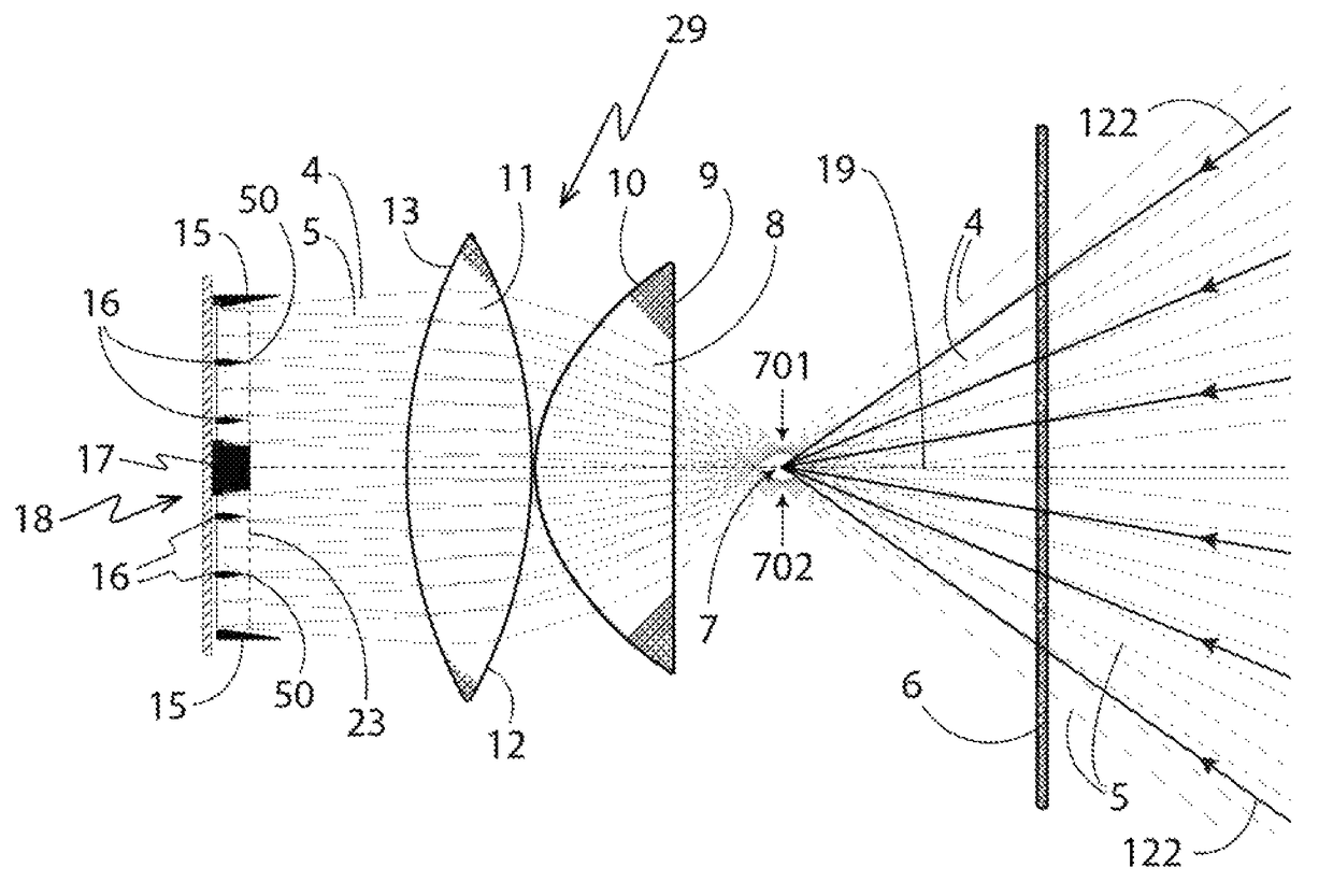
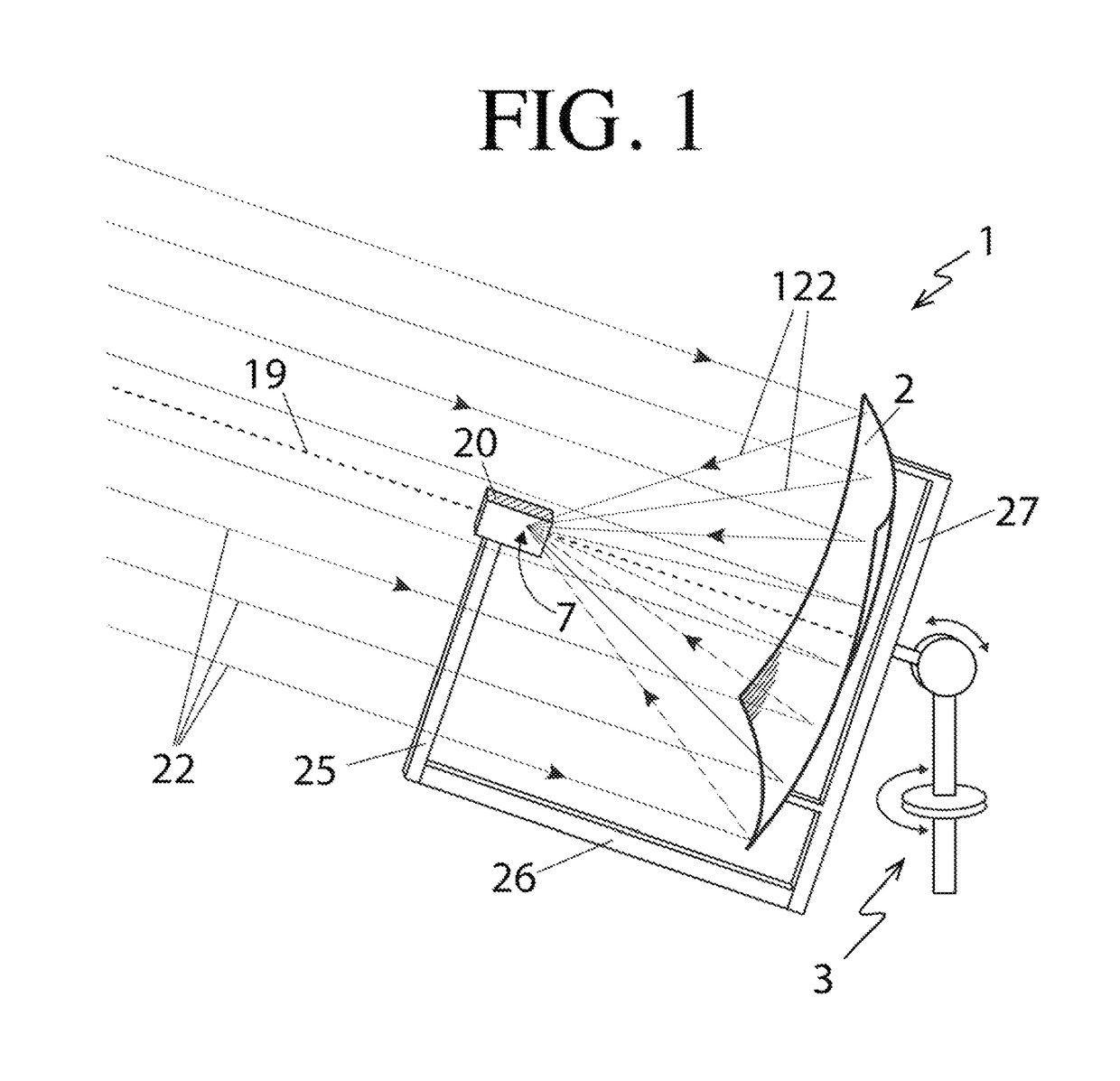
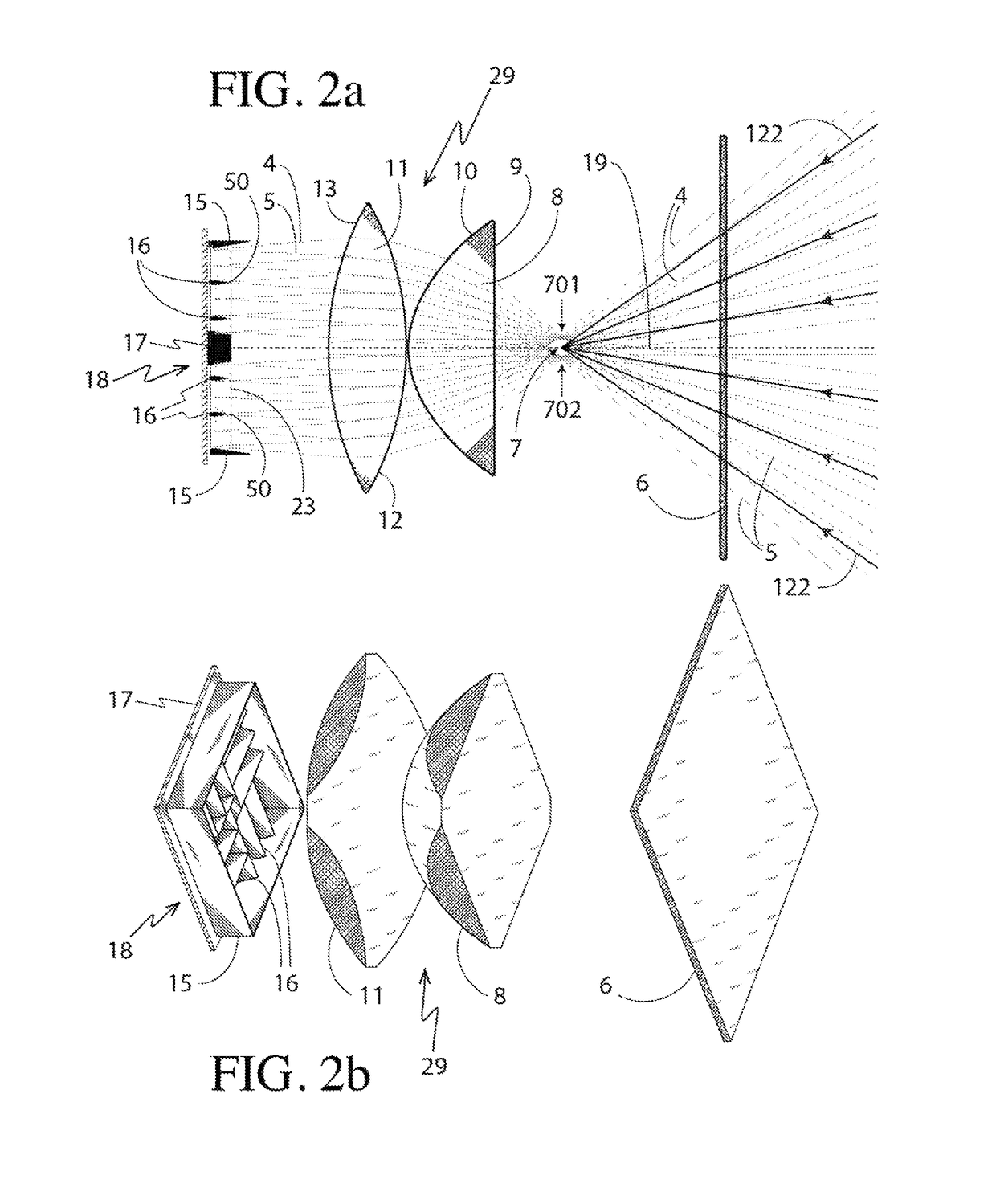
[0096]As shown in FIG. 1, solar rays 22 parallel to the axis 19 are reflected by the large reflector 2, and the reflected solar rays 122 converge upon the focus 7. Turning now to FIG. 2a, the reflected rays 122 pass through the focus 7 and impinge upon the lens 29. In accordance with a first embodiment of the present invention, the lens 29 shown in FIG. 2a is a telecentric lens 29.

[0097]FIG. 2a shows details of components comprising the PCU 20 according to a first embodiment of the present invention. In the illustrated example, a flat window 6 forms the entrance to the PCU 20. Within the PCU 20 and behind the window 6, is a two-element telecentric lens 29, a plurality of wedge reflectors 16, and a single planar array 18 of photovoltaic cells 30, which generate electricity. In this example, the telecentric lens 29 comprises a first piano-convex element 8, having a flat entrance surface 9 and a convex aspheric back surface 10. The telecentric lens 29 further comprises a second lens el...

second embodiment

[0128]A second embodiment of the present invention is described below which provides a different implementation of the power conversion unit or PCU 20 having a single lens element 70, and having photovoltaic cells 30 configured in four planar arrays 18.

[0129]Turning now to FIG. 17a, a second embodiment according to the present invention is shown comprising a PCU 20 having a single lens element 70. Solar rays 22 parallel to the axis 19, after reflection by the dish reflector 2, then converge as rays 122 in the PCU 20. The incoming light rays 122 converge to a focus 7. Additional converging rays 4 and 5 are shown which originate from opposite points on the edge of the sun's disc, and converge to the two corresponding focal points 701 and 702. The foci 7, 701 and 702 are formed within the single lens 70, which also forms the entrance window to the PCU 20 (as shown in FIG. 37).

[0130]The lens 70 shown in FIG. 17a comprises a single biconvex element with entrance surface 12 and exit surfa...


PUM


Abstract

An apparatus is disclosed for generation of electricity using sunlight focused onto multi junction photovoltaic cells having high conversion efficiency. The apparatus includes a large paraboloidal mirror of back-silvered glass, turned to the sun throughout the day, so as to provide an intense focus. Multiple photovoltaic cells are provided at the focus. The optics are configured to distribute sunlight without significant loss into separate regions matched to the photovoltaic cell size. A secondary optical system takes strongly focused sunlight near the focus of a single paraboloidal mirror and distributes it equally between the cells, and regions of equally concentrated sunlight are matched to cell size and are substantially co-planar, so that the cells may be grouped on flat circuit cards.

Description

CROSS REFERENCE TO RELATED APPLICATIONS[0001]This application is a U.S. National Phase filing under 35 U.S.C. § 371 of PCT / US2013 / 071974, filed on Nov. 26, 2013, which claims priority to U.S. Provisional Patent Application Ser. No. 61 / 797,168 filed on Nov. 30, 2012, both of which are incorporated herein by reference in their entirety.BACKGROUND OF THE INVENTION[0002]In the past, solar generators aimed at exploiting the high efficiency of multi-junction solar cells to generate electricity typically employed many small solar focusing optical systems for each individual photovoltaic cell. Such generators were deficient in that the packaged assemblies of numerous optical systems and cells were both large and complex, and consequently suffered from a relatively high cost that made such solar generators uncompetitive with alternative methods of generating electricity. Such generators also required large, unique facilities for their manufacture, and were expensive to transport from the fac...

Claims


Application Information

Patent Timeline
Patent Type & Authority Patents(United States)
IPC IPC(8): H02S40/22H01L31/054H02S20/32
CPCH02S40/22H01L31/0543H02S20/32H01L31/0547Y02E10/52
Inventor ANGEL, ROGER PCOUGHENOUR, BLAKE MSTALCUP, JR., THOMAS ELOVE, BRIAN
Owner THE ARIZONA BOARD OF REGENTS ON BEHALF OF THE UNIV OF ARIZONA
Why Eureka
Try Eureka