Projection optical system and projector

a technology of projection optical system and projector, which is applied in the direction of picture reproducers, picture reproducers using projection devices, instruments, etc., can solve the problems of increased width of rays that reach the concave mirror from the lens system, interference between incident light and outgoing light, and difficult glass block inserting, so as to prevent the influence of physical factors, reduce the second intermediate image, and achieve favorable balance between performance and size

Active Publication Date: 2018-08-28
NITTO OPTICAL CO LTD
View PDF20 Cites 1 Cited by
  • Summary
  • Abstract
  • Description
  • Claims
  • Application Information

AI Technical Summary

Benefits of technology

[0005]When inserting a glass block onto an optical path to control the optical path, with a system that uses a convex mirror, incident light to the convex mirror and outgoing light from the convex mirror will pass the glass block, resulting in interference between the incident light and the outgoing light. This means that it is difficult to insert a glass block. For systems that use a concave mirror, light flux that reaches the concave mirror on the enlargement side from a lens system spreads, and in particular, for a system that projects images with a wide angle, the width of rays that reach the concave mirror from the lens system increases, and it is difficult to insert a glass block so as to produce substantially the same effect for all light rays. On the other hand, the inventor of the present invention found that by using a first optical system that internally forms an intermediate image, it is possible to place the first intermediate image between a second intermediate image, which is formed between the first optical system and the first reflective surface, and the first image plane on the reducing side, and possible to suppress the spreading of rays that reach the first reflective surface from the first optical system. Accordingly, with the projection optical system according to the present invention, it is possible to insert a glass block that applies an effect to all rays that reach the first reflective surface from the first optical system and does not interfere with light outputted from the first reflective surface.
[0006]When projecting extremely wide-angle images onto the second image plane, the size (diameter) of the first reflective surface increases and to suppress an increase in diameter, the refractive power of the first optical system increases, making it difficult to correct various aberrations. By incorporating the first optical system that internally forms an intermediate image, it is possible to suppress the spreading of the light flux that reaches the first reflective surface from the first optical system. This means that it is possible to project extremely wide-angle images using a compact first reflective surface. In addition, by disposing a glass block that is a medium with high refractive power on an optical path that reaches the first reflective surface from the first optical system, it is possible to reduce the ray height to suppress an increase in the size of the first reflective surface without increasing the refractive power of the first optical system, in particular refractive power of the reducing side of the first optical system, which makes it possible to provide a projection optical system that is more compact.
[0012]In this projection optical system, it is desirable for a light emitting area Vs of the first image plane and an area I1s of the first intermediate image to satisfy a following condition. This makes it possible to provide a projection optical system with a favorable balance between performance and size.0.5<I1s / Vs<2.0  (5)
[0013]The glass block is disposed between the first optical system and the second intermediate image. By forming the second intermediate image outside the glass block, it is possible to prevent the influence of physical factors for the glass block, for example, scratches and dust from appearing in the second intermediate image, and possible to prevent a drop in the quality of the images that are finally projected onto the second image plane.
[0014]The glass block may include an incident surface on a first optical system side; an exit surface on a first reflective surface side; and a side surface that is between the incident surface and the exit surface, with the side surface being at least partially inclined with respect to the optical axis between the first optical system and the first reflective surface. As one example, the side surface may include a surface that is inclined so as to be substantially parallel to lower rays of the projecting light that reaches the second image plane from the first reflective surface. It is possible to suppress interference between the lower rays and the glass block. The side surface of the glass block may include an internally reflective surface that reflects rays that reach the first reflective surface from the first optical system.

Problems solved by technology

When inserting a glass block onto an optical path to control the optical path, with a system that uses a convex mirror, incident light to the convex mirror and outgoing light from the convex mirror will pass the glass block, resulting in interference between the incident light and the outgoing light.
This means that it is difficult to insert a glass block.
For systems that use a concave mirror, light flux that reaches the concave mirror on the enlargement side from a lens system spreads, and in particular, for a system that projects images with a wide angle, the width of rays that reach the concave mirror from the lens system increases, and it is difficult to insert a glass block so as to produce substantially the same effect for all light rays.
When projecting extremely wide-angle images onto the second image plane, the size (diameter) of the first reflective surface increases and to suppress an increase in diameter, the refractive power of the first optical system increases, making it difficult to correct various aberrations.

Method used


Image

  • Projection optical system and projector
  • Projection optical system and projector
  • Projection optical system and projector

Examples


Embodiment Construction

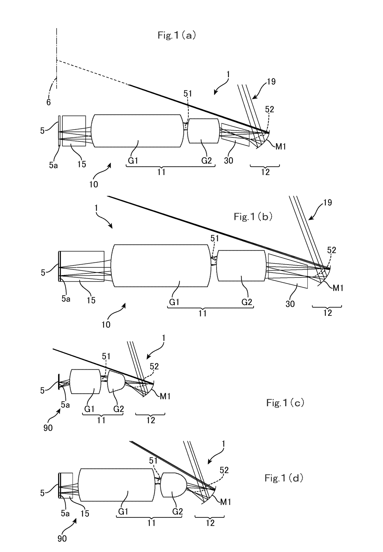
[0031]FIGS. 1(a) to 1(d) show several examples of projectors. The projector 1 includes a projection optical system 10 or 90 that projects light from an image forming plane (first image forming plane) 5a of a light modulator (light valve) 5 on a reducing side to a screen or wall surface (second image forming plane) 6 on an enlargement side. The light valve 5 is any device capable of forming an image such as an LCD, a digital mirror device (DMD), or an organic EL display, and may be a single panel-type device or a device that uses a method where images of different colors are individually formed. The light valve 5 may be a light emitting type or may be an illuminated type. When the light valve 5 is an illuminated type, the projector 1 further includes an illumination optical system (not illustrated). The screen 6 may be a wall surface, a white board, or the like, and the projector 1 may be a front projector, or may be arear projector that incorporates a screen.

[0032]The projection opt...


PUM


Abstract

A projection optical system (10) projects from a first image plane (5) on a reducing side to a second image plane (6) on an enlargement side. The projection optical system (10) includes a first optical system (11) that includes a plurality of lenses and forms a first intermediate image (51) formed inside the first optical system (11) by light incident from the reducing side into a second intermediate image (52) on the enlargement side of the first optical system (11); a second optical system (12) that includes a first reflective surface (M1) with positive refractive power which is positioned further to the enlargement side than the second intermediate image (52); and a glass block (30) that is disposed between the first optical system (11) and the first reflective surface (M1), the glass block (30) passing light rays from the first optical system (11) to the second intermediate image (52).

Description

TECHNICAL FIELD[0001]The present invention relates to a projection optical system of a projector.BACKGROUND ART[0002]Japanese Laid-Open Patent Publication No. 2004-258620 (hereinafter “Document 1”) discloses the realization of a projection optical system which uses an image forming optical system including a reflective surface to increase the size on the screen of projected images while reducing the projection space outside a projector apparatus and which is also capable of correcting chromatic aberration, and also discloses an image projecting apparatus that uses such projection optical system. To do so, Document 1 discloses that a first and a second optical system are disposed in that order from a light valve on the projection side of the light valve, the first optical system includes at least one refractive optical system and has positive refractive power, the second optical system includes at least one reflective surface with refractive power and has positive refractive power, a...

Claims


Application Information

Patent Timeline
Patent Type & Authority Patents(United States)
IPC IPC(8): H04N9/31G02B15/20G03B21/28G03B21/14G02B13/16
CPCH04N9/315G02B13/16H04N9/3141G03B21/147G03B21/28G02B15/20G02B17/08G02B17/0852G03B21/00G03B21/14
Inventor MATSUO, TAKAHIKO
Owner NITTO OPTICAL CO LTD
Why Eureka
Try Eureka