Beam distributor

a distributor and beam technology, applied in the field of beam distributors, can solve the problems of large energy loss of laser beams and difference between angles, and achieve the effect of suppressing the reduction of reflectivity

Active Publication Date: 2018-09-04
FANUC LTD
View PDF24 Cites 0 Cited by
  • Summary
  • Abstract
  • Description
  • Claims
  • Application Information

AI Technical Summary

Benefits of technology

[0005]In the beam distributor described in patent document 1, rotating the reflector changes a tilt angle of the reflection surface from an optical axis of a laser beam to be input. This results in difference between angles at which laser beams are to be input to the reflection surface of the reflector. If laser beams are input to the reflection surface of the reflector at different angles, the reflectivity of each of the laser beams may be reduced in a manner that depends on a rotational angle about the reflector. This causes large energy loss of the laser beams. Thus, a beam distributor capable of suppressing reflectivity reduction has been desired.
[0006]The present invention is intended to provide a beam distributor capable of suppressing reflectivity reduction.
[0008](2) The beam distributor described in (1), preferably includes a scattered light sensor (photodiode 5 described later, for example) that detects scattered light of a reflected beam at one of the beam exits changed in direction by the beam turning part. The angular information in the storage is preferably changed so as to minimize a value detected by the scattered light sensor while the reflected beam is output to one of the beam exits.
[0011]According to the present invention, a beam distributor capable of suppressing reflectivity reduction can be provided.

Problems solved by technology

This results in difference between angles at which laser beams are to be input to the reflection surface of the reflector.
This causes large energy loss of the laser beams.

Method used


Image

  • Beam distributor
  • Beam distributor
  • Beam distributor

Examples


Embodiment Construction

[0015]An embodiment of the present invention will be described below by referring to the drawings.

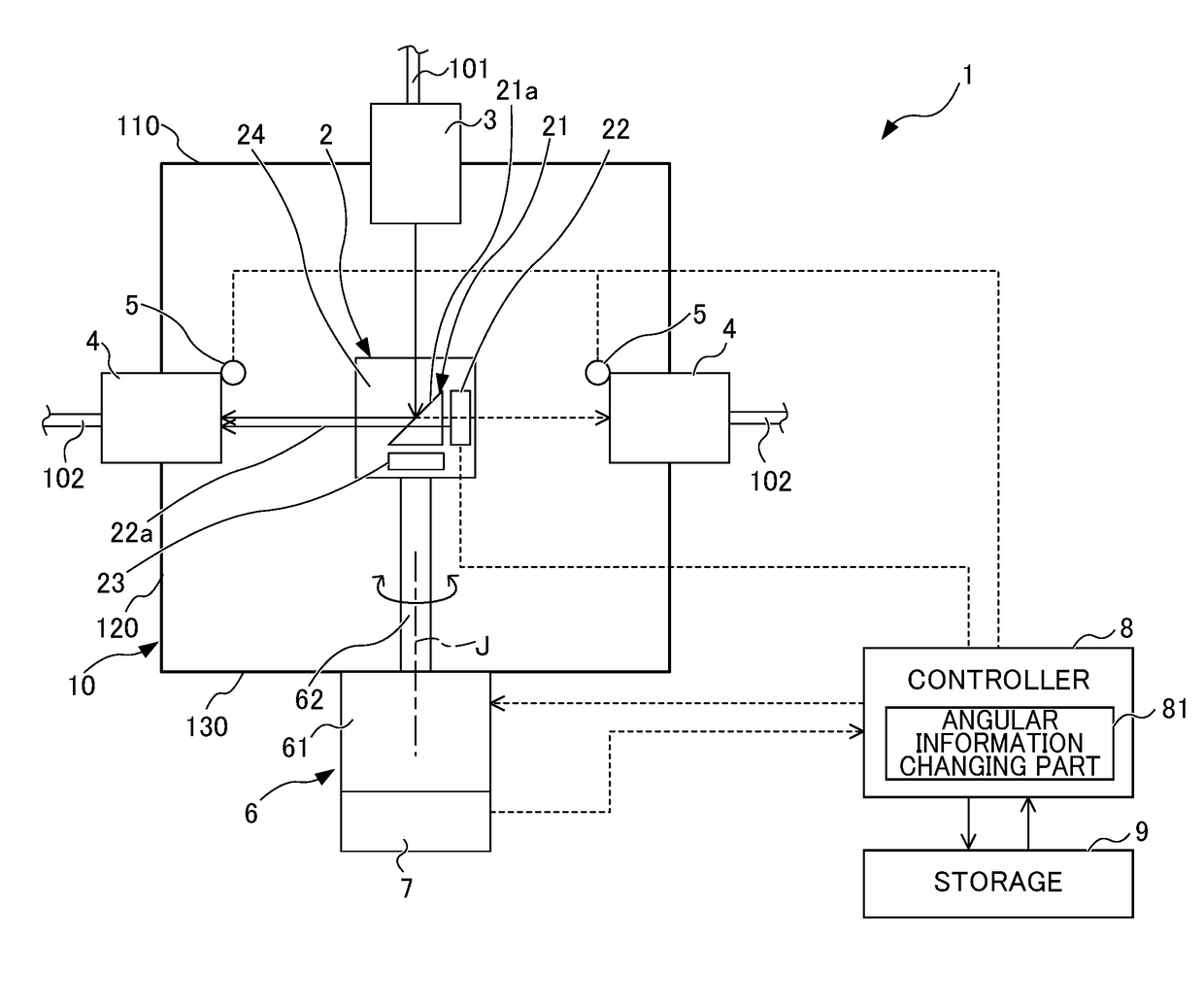
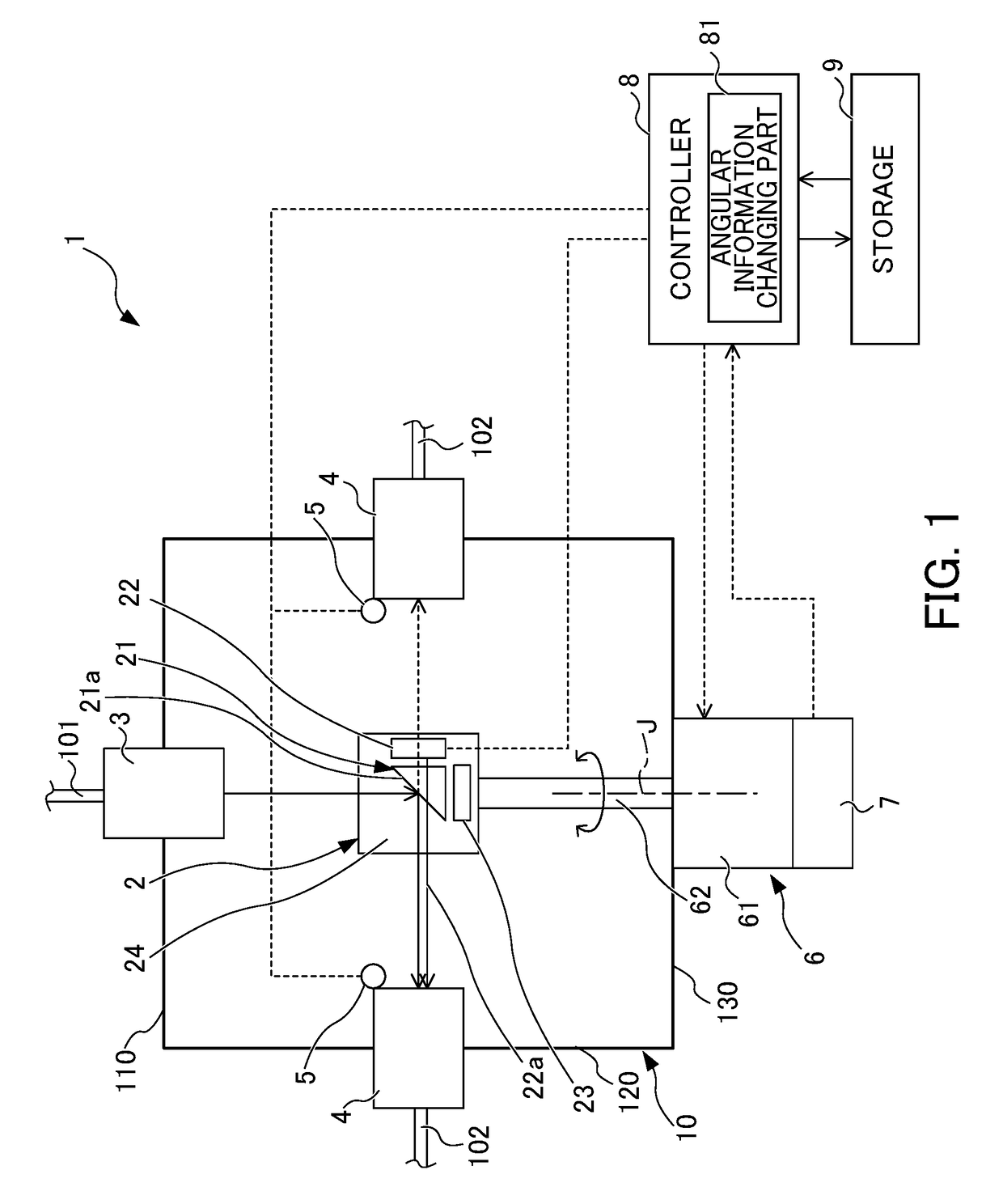
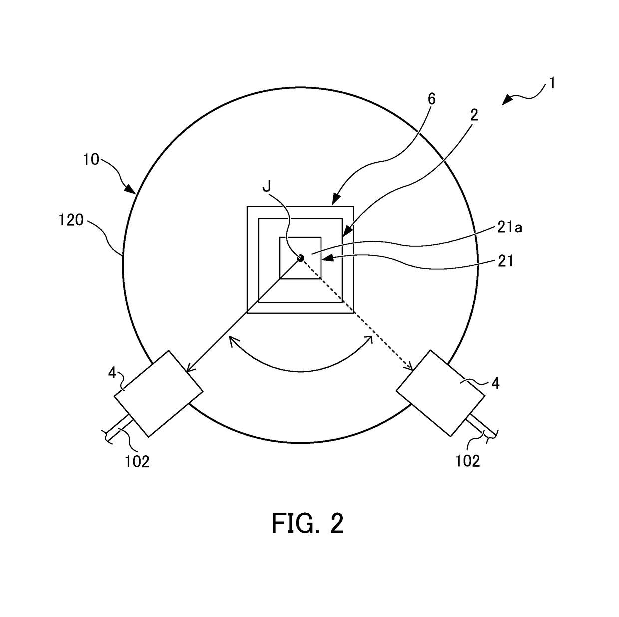
[0016]FIG. 1 shows the configuration of a beam distributor 1 according to the embodiment. FIG. 2 shows a tilted reflector 21 of the beam distributor 1 according to the embodiment when viewed in the direction of a rotary axis J. FIG. 3 shows an input angle about a laser beam input to the tilted reflector 21 according to this embodiment determined by rotation of the tilted reflector 21.

[0017]The beam distributor 1 according to this embodiment is a device for selectively switching an input beam (laser beam, laser light) to any of multiple output-side optical fibers 102 after the beam is output from a laser device (not shown in the drawings) and then input through an input-side optical fiber 101. The laser beam selectively switched by the beam distributor 1 is caused to propagate through the output-side optical fiber 102 to be used for welding or cutting during laser machining.

[0018]As show...


PUM


Abstract

The beam distributor includes a housing, at least one beam entrance, two or more beam exits, a motor, and a beam turning part fixed to a rotary axis member of the motor and changing a direction of a beam input to the inside of the housing through the beam entrance so as to guide the input beam to the beam exit. A rotary axis of the motor is arranged parallel to an optical axis of the beam so as to input the beam to the beam turning part at a constant angle independently of a rotational angle about the rotary axis of the motor. The beam exit is arranged in a direction to which the direction of the beam is changed by the beam turning part in response to rotation of the rotary axis member. A storage stores an angular information recorded in advance about the rotary axis.

Description

BACKGROUND OF THE INVENTION[0001]This application is based on and claims the benefit of priority from Japanese Patent Application No. 2016-205259, filed on 19 Oct. 2016, the content of which is incorporated herein by reference.FIELD OF THE INVENTION[0002]The present invention relates to a beam distributor.RELATED ART[0003]According to a beam distributor conventionally known, multiple optical fibers are switched to select one optical fiber and one laser beam is caused to propagate through the selected optical fiber (see patent document 1). The beam distributor described in patent document 1 is configured in such a manner that a reflector is rotated by a rotary drive motor to a predetermined reflection position and a laser beam is reflected on a reflection surface of the reflector, thereby switching the laser beam in direction input through a beam entrance so as to make the laser beam propagate through one of multiple optical fibers.[0004]Patent Document 1: Japanese Unexamined Patent ...

Claims


Application Information

Patent Timeline
Patent Type & Authority Patents(United States)
IPC IPC(8): G02B6/32G02B6/35G02B6/36G02B6/42G02B6/12
CPCG02B6/3598G02B6/352G02B6/359G02B6/3604G02B6/4204G02B6/3582G02B2006/12121G02B6/3512G02B6/3568G02B6/4296G02B6/29361
Inventor MATSUDA, MUNEKAZU
Owner FANUC LTD
Why Eureka
Try Eureka