
Device for facilitating a chemical reaction

a technology of chemical reaction and device, which is applied in the direction of physical/chemical process catalysts, packaging foodstuffs, packaged goods, etc., can solve the problems of increasing the reaction time required for completing chlorine, restricting the “breathability” of the shell, and providing one cavity, etc., to facilitate the reaction

Active Publication Date: 2018-10-02
SCHROETER TODD
View PDF9 Cites 0 Cited by
  • Summary
  • Abstract
  • Description
  • Claims
  • Application Information

AI Technical Summary

Benefits of technology

[0013]A principal object of the present invention is to provide a device for facilitating a chemical reaction between a liquid catalyst and one or more dry reactants within device to produce a gas and / or liquid that is ultimately released into air and / or liquid. A feature of the device is the generation of a gas by acid activation. Another feature of the device is enclosure or packet fabrication material that encases the dry reactants and that allows the liquid catalyst to penetrate the packet relatively quickly and engage the dry reactants therein. An advantage of the device is that the one or more dry reactants are totally enclosed in a packet, and in the case of two or more reactants being present, the two or more reactants are separated and totally enclosed within the packet in cooperatively configured chambers, each chamber being completely filled with a respective dry reactant, thereby allowing the totally enclosed one or more dry reactants to be manually disposed in the liquid catalyst. Another advantage of the device is that the generation of a gas by acid activation occurs without the use of an external force to rupture the packet. Yet another advantage of the device is that the generation of a gas by acid activation occurs without the addition of a wick member to absorb and transport the liquid catalyst into the packet. Still another advantage of the device is that a material for fabricating the packet allows a relatively large quantity of water to flow relatively quickly into the packet to engage the internal components, the material of fabrication also allowing generated chlorine dioxide gas to escape the packet relatively fast and into the surrounding air and / or water. Another advantage of the device is that the material of fabrication allows water through the shell, yet the material resists atmospheric moisture to prevent premature activation of the internal components. Another advantage of the device is that the packets are rigid and therefore do not change shape after disposing dry reactants into the chambers, resulting in continuously full chambers of the dry chemicals that maintain a constant configuration within the packet, which causes consistent chlorine dioxide generation irrespective of packet orientation.
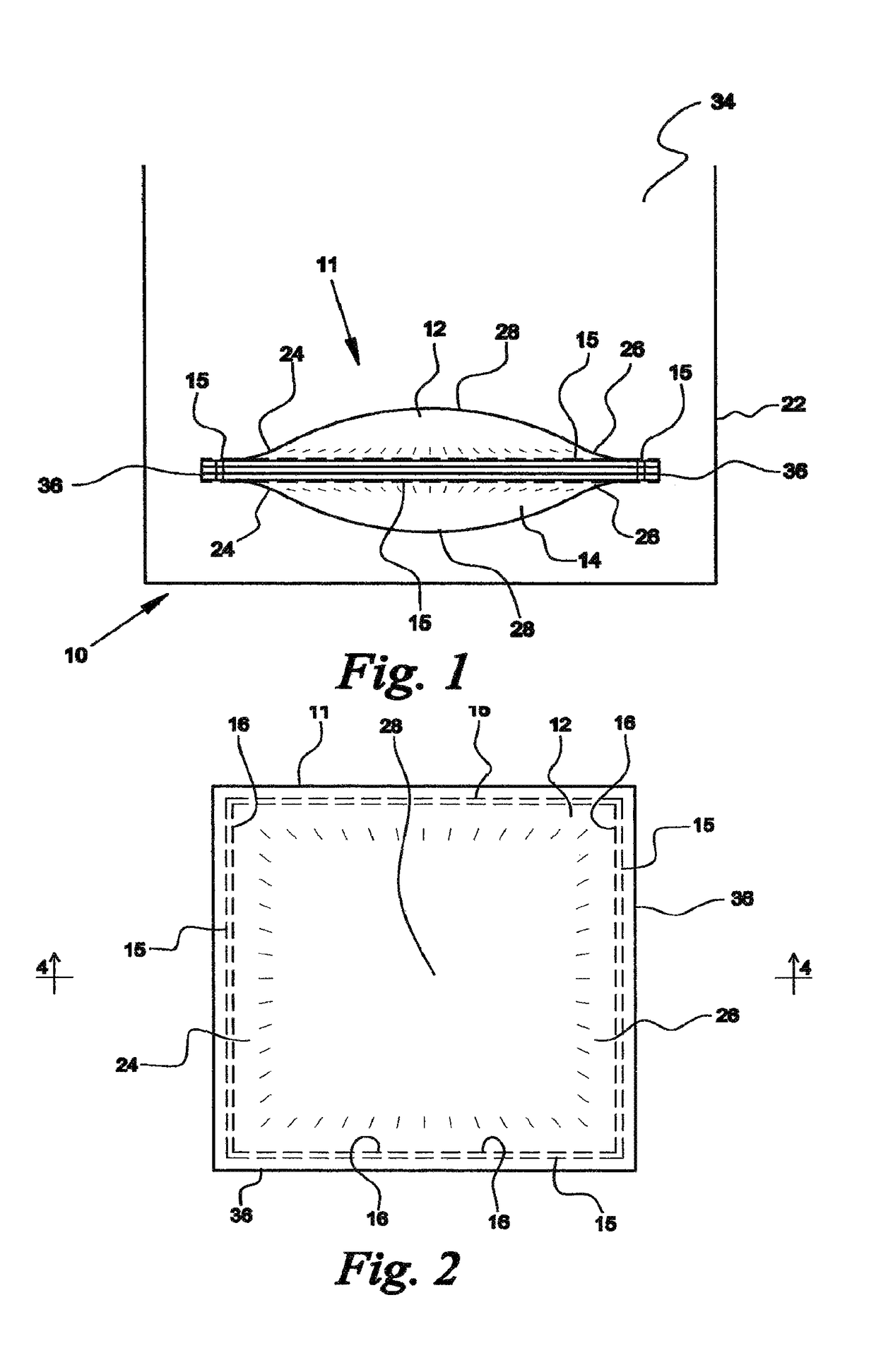
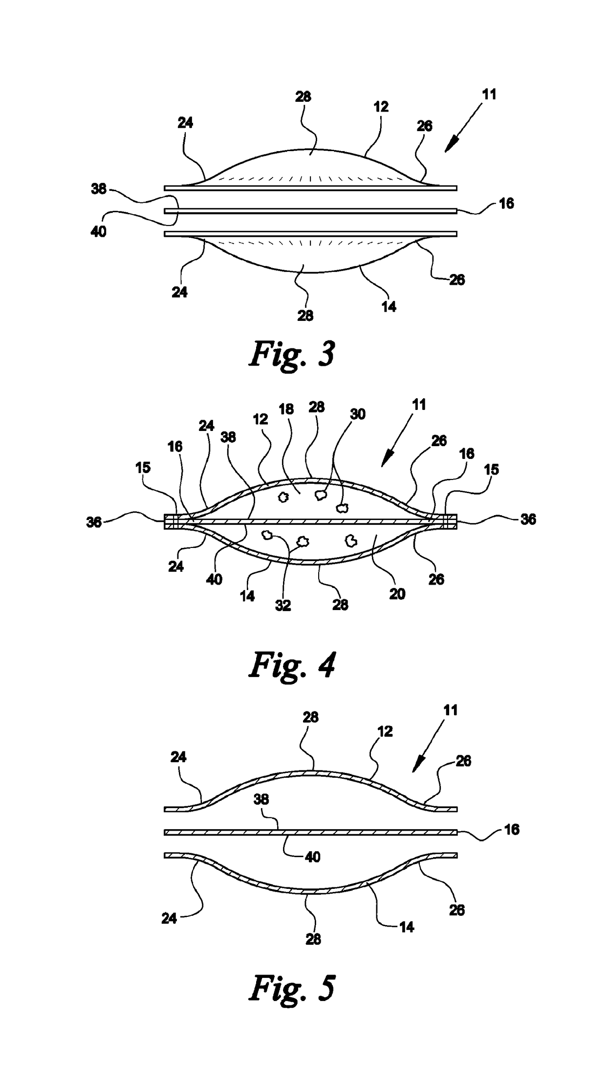
[0015]Yet another object of the present invention is to provide a device that facilitates generation of chlorine dioxide gas for release into water. A feature of the device is a packet having an upper and lower members fabricated from a compressed sponge cloth with a dissolvable member disposed between and enclosed by the upper and lower members such that upper and lower chambers are formed having substantially equal volumes. Another feature of the device is a packet having an upper chamber substantially filled with sodium chlorite, and having a lower chamber substantially filled with an acid mixture. An advantage of the device is that compressed sponge cloth material for fabricating the packet allows a relatively large quantity of water to seep relatively quickly into the packet to engaging and completely filling the internal components, the material of fabrication also allowing generated chlorine dioxide gas to escape the packet after an incubation period into the surrounding water. An advantage of the device is that water absorbed by the compressed sponge cloth has sufficient quantity to transform the sodium chlorite and the dry acid mixture into slurries quickly to dissolve the dissolvable member to allow the slurries to engage and ultimately react to generate chlorine dioxide gas that ultimately passes through the upper and lower members in relatively large quantities into a surrounding liquid to be disinfected and / or deodorized.
[0016]Still another object of the present invention is to provide a device that includes a packet fabricated from material that allows a relatively large quantity of water to flow relatively quickly into the packet to engage the internal components, the material of fabrication also allowing generated chlorine dioxide gas to escape the packet through the upper member relatively fast and into the surrounding air, the material of fabrication ultimately absorbing all water in a holder member that the packet is disposed in. A feature of the device is an upper member fabricated from compressed cellulose sponge and a lower member fabricated from cellulose cloth material. The compressed cellulose cloth and compressed cellulose sponge have closed pores and fiber structure when compressed, the pores ultimately opening when the lower and upper members absorb water, thereby allowing generated chlorine dioxide gas to escape the joined upper and lower members. An advantage of the device is that the compressed cellulose cloth material and compressed sponge material promote retention of sodium chlorite and acid slurries in corresponding upper and lower chambers until the reaction for generating chlorine dioxide gas is complete and without leaving any residue of sodium chlorite or acid. Another advantage of the device is that the joined upper and lower members of compressed sponge material and compressed cellulose cloth material retains the absorbed water during the entire reaction time for forming chlorine dioxide gas, and continues to retain the water after the reaction has completed, thereby allowing the packet and absorbed water to be disposed of without any appreciable water residue in the holder member.
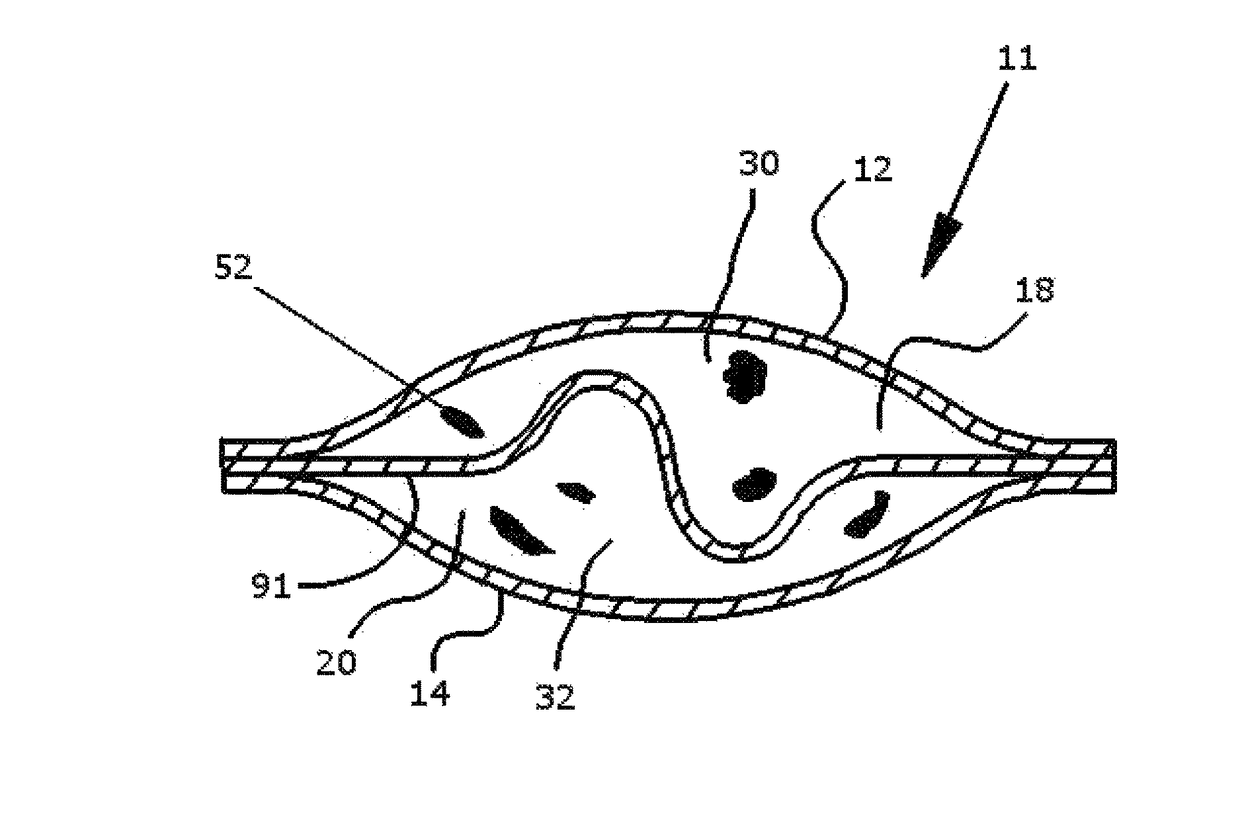
[0017]Another object of the present invention is to provide a device that includes a dissolvable member having a configuration that promotes a relatively faster and more complete chlorine dioxide gas generation and conversion rates. A feature of the device is a dissolvable member having an undulating or “wave” configuration that provides a trough or recess that receives sodium chlorite therein to maintain the sodium chlorite in the recess irrespective of the orientation of the packet. Another feature of the device is that the wall of the recess of the dissolvable member provides more surface area than a planar dissolvable member, thereby increasing cooperating quantities of sodium chlorite and acid mixture disposed adjacently on opposite sides of the dissolvable member. An advantage of the device is that when the dissolvable member is dissolved by acid and sodium chlorite slurries, the increased quantities of sodium chlorite and acid slurries that immediately mix together ultimately generates chlorine dioxide gas at a faster rate than the gas rate generated by relatively smaller slurry quantities that mix after a planar dissolvable member is dissolved. Another advantage of the device is that chlorine dioxide gas generation rate for a packet can be increased or decreased by correspondingly increasing or decreasing the surface area of the trough or recess, and the surface area of the recess is varied by correspondingly changing the configuration and / or dimensions of the dissolvable member.
[0019]The invention further provides facilitating a chemical reaction comprising an upper member having a predetermined configuration; a lower member having a predetermined configuration; a dissolvable member disposed between and ultimately enclosed by said upper and lower members such that upper and lower chambers are formed having substantially equal volumes, said upper chamber ultimately receiving a dry sodium chlorite mixture and said lower chamber ultimately receiving a dry acid mixture, whereupon, said upper and lower members are joined, thereby sealing said upper and lower chambers and enabling said joined upper and lower members to be disposed in water such that said lower member engages the water first, said joined lower and upper members ultimately swelling with absorbed water until all water has been absorbed; and a holder member for receiving a predetermined quantity of water and said joined upper and lower members with said dissolvable member there-between, whereby said upper and lower member configurations cooperate to allow a predetermined quantity of water to engage said dry acid and sodium chlorite mixtures to ultimately form slurries to dissolve said dissolvable member to allow said slurries to engage and ultimately react to generate chlorine dioxide gas that ultimately passes through said upper and lower members and into a space to be disinfected and / or deodorized, said upper and lower members being dimensioned and configured to cooperate with selected quantities of dry sodium chlorite and dry acid mixtures to generate a predetermined quantity of chlorine dioxide gas over a predetermined time period, said predetermined quantity of water being absorbed relatively quickly by said lower member, then absorbed by said upper member after said joined lower and upper members are disposed in said water.

Problems solved by technology

The problem with conventional non-electrically powered chlorine dioxide gas generators using dry sodium chlorite and an acid has been the membrane shells forming the cavities that receive the dry sodium chlorite and acid.
Unfortunately, the water protective membranes have increased the reaction time required for completing the chlorine dioxide gas generation from the combining of the sodium chlorite and acid after exposure to water.
Further, although the membranes are semi-permeable to chlorine dioxide gas, the flow of chlorine dioxide gas is restricted through the membranes during gas generation thereby restricting “breathability” of the shell.
Another problem with prior art chlorine dioxide gas generators is that only one cavity is provided to receive a mixture of sodium chlorite and acid.
The mixing of the reactants results in inconsistencies and varying contact ratios between the sodium chlorite and acid resulting in varying quantities of chlorine dioxide gas being generated when water engages the reactants.
When water initially engages the internal components adjacent to the wick member, then travels to internal components further from the wick member, varying amounts sodium chlorite react with varying amounts of acid, thereby providing slower and / or incomplete reactions between the sodium chlorite and acid, resulting in wasted residual portions of each internal component which must be discarded and which did not generate any chlorine dioxide.
In general, the prior art devices and methods do not provide sufficient surface area to fully utilize all of the supplied chemicals and to cause a complete reaction between the sodium chlorite and acid such that there is no “unused” portions of either component, which results in a less than maximum formation of chlorine dioxide gas.
Further, the prior art devices do not use a material for constructing the packets or shells that are capable of allowing a relatively large quantity of water to flow relatively quickly through the shell to engage the internal components, and that allows generated chlorine dioxide gas to escape relatively fast through shell and into the surrounding air and / or water.
Another problem with the prior art is that the packets are not rigid and therefore change shape after disposing dry reactants into chambers, resulting in less than full chambers, non-uniform distribution of the dry chemicals in the packet, and dry chemicals that vary in configuration when the orientation of the packet is changed, thereby reducing chlorine dioxide generation and allowing residual unused chemicals.

Method used


Image

  • Device for facilitating a chemical reaction
  • Device for facilitating a chemical reaction
  • Device for facilitating a chemical reaction

Examples


Embodiment Construction

[0043]Referring now to FIGS. 1-5, a device fabricated from compressed cellulose for facilitating a chemical reaction between a liquid catalyst and one or more dry reactants within the device to produce a gas or liquid that is ultimately released into air or liquid is denoted as numeral 10. One use for the device 10 of the present invention is the generation of a gas by acid activation. Examples of acid activation include, but are not limited to acid activation of a carbonate via calcium carbonate combined with citric acid in the presence of moisture to form carbon dioxide, acid activation of a sulfite via sodium bisulfite or potassium bisulfite with fumaric acid and / or potassium bitartrate in the presence of moisture to form sulfur dioxide gas, and acid activation of a nitrite via sodium nitrite or potassium nitrite in the presence of moisture to form nitrogen dioxide gas.

[0044]A preferred use of the device 10 is the generation of chlorine dioxide gas for release into air or water. ...


PUM

PropertyMeasurementUnit
specific gravityaaaaaaaaaa
diameteraaaaaaaaaa

Abstract

A device for facilitating a chemical reaction while submerged in a liquid catalyst includes an upper member, a lower member, and a dissolvable member disposed between and ultimately enclosed by said upper and lower members such that upper and lower chambers are formed having substantially equal volumes. The upper chamber may receive a dry sodium chlorite and the lower chamber may receive a dry acid mixture. In order to keep the device submerged in the liquid catalyst, an inert ballast may also be added to the upper and / or lower chamber, such as glass shards.

Description

CROSS-REFERENCE TO RELATED APPLICATIONS[0001]This application is a continuation-in-part application which claims priority to U.S. patent application Ser. No. 14 / 703,538, filed on May 4, 2015, which is a continuation of U.S. patent application Ser. No. 13 / 805,184 (now U.S. Pat. No. 9,050,570), which is a 371 U.S. National Stage of International Application No. PCT / US2011 / 041011, filed on Jun. 18, 2011, which claims priority to and the benefit of U.S. Provisional Application No. 61 / 397,931, filed on Jun. 18, 2010. The contents of the above applications are incorporated herein by reference in their entirety.BACKGROUND OF THE INVENTION[0002]1. Field of the Invention[0003]This invention relates to a device for facilitating a chemical reaction, and more particularly, to a device and method for facilitating the generation of chlorine dioxide gas for release into air or water.[0004]2. Background of the Prior Art[0005]Chlorine dioxide gas is a well-known disinfectant and deodorizing agent th...

Claims


Application Information

Patent Timeline
Patent Type & Authority Patents(United States)
IPC IPC(8): B01J7/02C01B11/02B01J8/00B65B29/10B65B7/02A61L2/18
CPCB01J7/02B01J8/008B65B7/02C01B11/024B65B29/10B01J2208/00814A61L2/18A61L2202/11A61L2/20A61L9/015C02F1/685C02F1/76B01J35/04B01J35/12C01B11/023
Inventor SCHROETER, TODD
Owner SCHROETER TODD
Learn More