System and method for providing tools on a machine tool and machine tool having a tool change system

a technology of tool change and machine tool, which is applied in the direction of manufacturing tools, metal-working machine components, positioning apparatuses, etc., can solve the problems of no tool can be provided, and loss with respect to auxiliary process time, so as to optimize the tool loading of the two tool magazines, reduce the auxiliary process time, and reduce the effect of auxiliary process tim

Inactive Publication Date: 2018-10-16
DECKEL MAHO PFRONTEN GMBH
View PDF43 Cites 1 Cited by
  • Summary
  • Abstract
  • Description
  • Claims
  • Application Information

AI Technical Summary

Benefits of technology

[0020]A further advantage of the invention is that the combination of two tool magazines offers the possibility of carrying out the tool fracture monitoring, the taper cleaning or the tool identification optionally in both the first and second tool magazines. The second tool magazine is preferably adapted to carry out the tool fracture monitoring, the taper cleaning or the tool identification in such a way that they can take place e.g. at the same time as a tool change carried out by the first tool magazine to further reduce the auxiliary process times.
[0021]In this context, the terms “feeding device” and “transfer apparatus” according to the invention are understood to refer to the function. It is advantageous for the transfer apparatus and the first feeding device to be structurally designed as a module, by means of which tools are moved between the first tool magazine and the spindle and by means of which tools are moved between the first tool magazine and the second tool magazine. The transfer apparatus here preferably takes tools provided at a predetermined transfer position by the second feeding device or the transfer apparatus provides the second feeding device with tools removed from the first tool magazine at a predetermined transfer position. In other words, the first feeding device is used in this case as a transfer apparatus to feed tools from the second tool magazine to the first tool magazine and / or to return tools from the first tool magazine into the second one. According to this embodiment, the first feeding device has a dual function to avoid the provisioning of a separate transfer apparatus: It performs the tool change on the spindle and optimizes the tool loading of the two tool magazines in such a way that the tools required on the workpiece on account of the predetermined processing steps are provided promptly in the first tool magazine. The first feeding device is preferably adapted to exchange tools between the first and second tool magazines while the workpiece is processed on the spindle so as to further reduce the auxiliary process times.
[0022]However, it is also possible to use an additional feeding device as a transfer apparatus, said feeding device being adapted to feed tools stored in the second tool magazine to the first magazine and vice versa.
[0023]It is also possible for the transfer apparatus and the second feeding device to be made as a module, by means of which tools are removed from storage areas of the second tool magazine and are moved between the second tool magazine and the first tool magazine to exchange tools between the second tool magazine and the first tool magazine.
[0024]A further advantage of the invention is that the transfer apparatus can also be adapted to feed tools from the second tool magazine directly to the machine tool. The possibility of feeding tools from the second tool magazine optionally directly to the machine spindle or initially to the first tool magazine for intermediate storage, increases the flexibility in the tool provisioning so as to avoid a “bottleneck” at the first tool magazine and, depending on the production flow and the required tool sequence, to choose the tool provisioning strategy enabling the optimum production flow. If the transfer apparatus and the second feeding device are made as a module, the feeding device of the second tool magazine, e.g. the manipulator of a matrix magazine, can advantageously also be adapted to feed tools from the second tool magazine optionally directly to the machine spindle or to the first tool magazine for intermediate storage.
[0025]It is especially advantageous for the transfer apparatus to be adapted to optimize the loading of the two tool magazines by an exchange of tools between the first and second tool magazines in such a way that in each case the tools required for the next n processing steps (n≥1) on the spindle are available in the first tool magazine. Depending on the type and storage capacity of the tool magazine, the value for n can be determined e.g. in such a way that during the next n processing steps it is also possible to carry out a loading step of the second tool magazine on the workpiece. The advantage is that also during a loading step of the supply magazine during which no tool exchange is possible with the first tool magazine, no losses result with respect to the auxiliary process times. As a result, there are no waiting times on the tool spindle since all tools required for the next n processing steps are available in the first tool magazine.

Problems solved by technology

However, in connection with the above mentioned tool magazines it is often impossible to avoid that, while the tools are provided or resorted, the machine tool has already concluded the processing step performed on the workpiece and requires the next tool.
If the provisioning periods of the tool magazine are too long, idle times result for the machine spindle, thus leading to a loss with respect to the auxiliary process time.
Furthermore, it is disadvantageous that, while a tool magazine is additionally loaded, no tool can be provided at a loading station, and therefore loading operations of this type can result in a loss with respect to the auxiliary process time.
However, magazines having many tool areas usually need a relatively large set-up area which is often limited in particular in the direct vicinity of the tool spindle.
However, this system is likewise limited with respect to the tool transport capacity.

Method used


Image

  • System and method for providing tools on a machine tool and machine tool having a tool change system
  • System and method for providing tools on a machine tool and machine tool having a tool change system
  • System and method for providing tools on a machine tool and machine tool having a tool change system

Examples


Embodiment Construction

[0061]Preferred embodiments of the present invention are described in more detail below by way of example and in exemplary fashion with reference to the enclosed drawings.

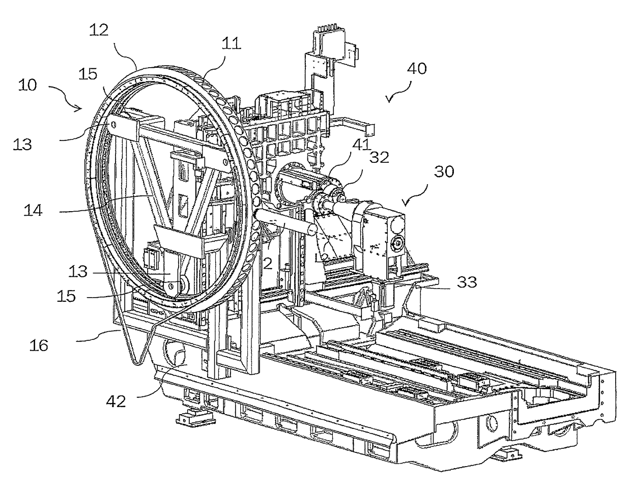
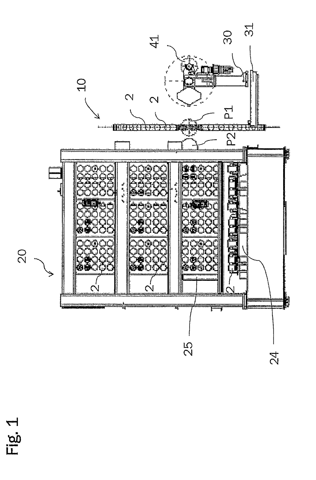
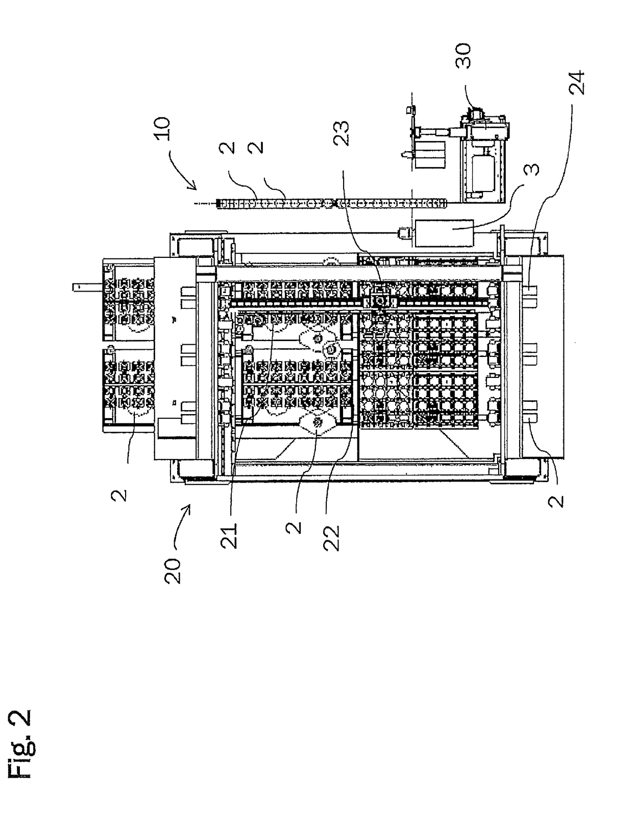
[0062]FIG. 1 shows a front view of an embodiment of the system according to the invention for changing and providing tools on a machine tool, wherein the first tool magazine is made as a wheel-type magazine 10 and the second tool magazine 20 is made as a matrix magazine. The tool magazines 10 and 20 store a plurality of tools 2 and provide them, if required, to the tool spindle 41 of a machine tool or receive a tool 2 which is no longer required by the tool spindle 41 for storage. The wheel-type magazine 10 and the matrix magazine 20 can be loaded with all common tools 2 for the non-cutting and cutting production. Only the tool spindle 41 of the machine tool is shown in FIG. 1 to elucidate the inventive principle.

[0063]The wheel-type magazine 10 is upright, i.e. the circumferential line, along which the radially ar...


PUM


Abstract

The present invention relates to a system, an apparatus and a method for providing tools on a machine tool. The system includes a first tool magazine for accommodating a plurality of tools; a first feeding device which is adapted to remove tools from the first tool magazine and feed them to the spindle; at least one second tool magazine for accommodating a plurality of tools; a second feeding device which is adapted to remove tools from the second tool magazine and provide them at a predetermined transfer position; and a transfer apparatus which is adapted to feed tools removed from the second tool magazine to the first tool magazine, with the result that the second tool magazine serves as a supply magazine for the first tool magazine.

Description

[0001]The present invention relates to a system and a method for providing tools on a machine tool and to a machine tool which serves for processing a workpiece and includes a tool change system.BACKGROUND OF THE INVENTION[0002]Systems for providing tools on a machine tool and tool magazines for tool storage of a machine tool are known in various designs from the prior art. Tool change systems are used in milling machining centers, for example, to reduce the auxiliary process time of the respective processing machine, i.e. the so-called chip-to-chip times, for example.[0003]By means of tool change systems of this type, tools are transferred from a tool magazine to a machining spindle of a machine tool and / or from the latter back into the tool magazine, if required. This is optionally performed in fully automated and program-controlled fashion.[0004]For this purpose, today's tool magazines for machine tools accommodate a plurality of tools for tool storage and supply them to the mach...

Claims


Application Information

Patent Timeline
Patent Type & Authority Patents(United States)
IPC IPC(8): B23Q3/157B23Q3/155
CPCB23Q3/15539B23Q3/1554B23Q3/1572B23Q3/15503B23Q3/15526B23Q3/15773B23Q3/15713Y10T483/1786B23Q2003/155435Y10T483/10Y10T483/175Y10T483/1767B23Q3/15722B23Q2003/155449
Inventor KRAFT, OLIVERRIEDEL, SEBASTIANTRENKLE, MICHAEL
Owner DECKEL MAHO PFRONTEN GMBH
Why Eureka
Try Eureka