Interposer manufacturing method

a manufacturing method and interposer technology, applied in the manufacture of tools, grinding machine components, welding/soldering/cutting articles, etc., can solve the problems of increased fraction defect, cutting blade, heat resistance problem, etc., and achieve the effect of improving the heat resistance of the interposer using the glass substrate and easy separation of the multi-layer member

Active Publication Date: 2018-10-30
DISCO CORP
View PDF8 Cites 0 Cited by
  • Summary
  • Abstract
  • Description
  • Claims
  • Application Information

AI Technical Summary

Benefits of technology

[0006]It is therefore an object of the present invention to provide an interposer manufacturing method which can improve the heat resistance of an interposer using a glass substrate.
[0010]According to the interposer manufacturing method of the present invention, the groove (cut groove or laser processed groove) having a depth not reaching the glass substrate is first formed on the multilayer member along each division line, and the glass substrate is next cut along each groove by using the cutting blade having a thickness smaller than the width of each groove. Accordingly, a thin portion of the multilayer member is left at an end portion (peripheral portion) of each interposer manufactured. In the case of a conventional interposer, the multilayer member has a thick end portion, so that when the conventional interposer is heated, a large force due to a difference in coefficient of thermal expansion between the multilayer member and the glass substrate may be applied to the end portion of the interposer, causing easy separation of the multilayer member from the glass substrate. To the contrary, the multilayer member of the interposer manufactured by the present invention has a thin end portion (thin peripheral portion). Accordingly, as compared with the conventional interposer, the interposer manufactured by the present invention can reduce the possibility that a large force separating the multilayer member may be applied to the end portion of the interposer. That is, even when the interposer manufactured by the present invention is heated, the multilayer member is resistant to separation from the glass substrate. Thus, the heat resistance of the interposer using the glass substrate can be improved according to the interposer manufacturing method of the present invention.

Problems solved by technology

However, the interposer manufactured by this method using the cutting blade has a problem in heat resistance.
Specifically, the result of a temperature cycling test (TCT) conducted to this interposer depicts that cracks were produced in the glass substrate and the multilayer member was separated from the glass substrate, causing an increase in fraction defective.

Method used


Image

  • Interposer manufacturing method
  • Interposer manufacturing method
  • Interposer manufacturing method

Examples


Embodiment Construction

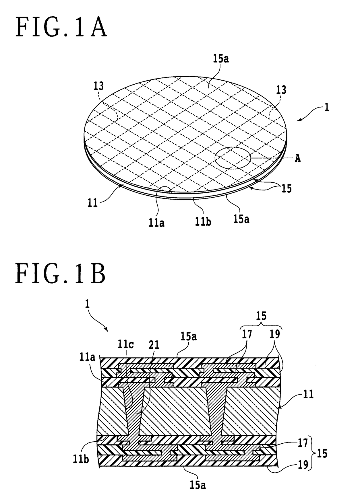
[0019]A preferred embodiment of the present invention will now be described with reference to the attached drawings. The interposer manufacturing method according to this preferred embodiment is a method of manufacturing a plurality of interposers from a material substrate including a glass substrate and a multilayer member. This method includes a cut groove forming step (see FIGS. 2A and 2B) and a dividing step (see FIG. 3A). In the cut groove forming step, an exposed surface of the multilayer member is cut by a cutting blade (first cutting blade) along a plurality of division lines set on the glass substrate, thereby forming a cut groove on the multilayer member along each division line, in which each cut groove has a depth not reaching the glass substrate (i.e., the depth of each cut groove is slightly less than the thickness of the multilayer member). In the dividing step, the glass substrate is cut along each cut groove by another cutting blade (second cutting blade) having a t...


PUM

PropertyMeasurementUnit
grain sizeaaaaaaaaaa
thicknessaaaaaaaaaa

Abstract

A plurality of interposers are made from a material substrate. The material substrate includes a glass substrate partitioned by a plurality of crossing division lines to define a plurality of separate regions. A multilayer member is provided on a first surface or a second surface opposite to the first surface of the glass substrate and has an insulating layer and a wiring layer. An exposed surface of the multilayer member is cut along each division line by using a first cutting blade to form a cut groove on the exposed surface of the multilayer member, the cut groove having a depth not reaching the glass substrate. The glass substrate is cut along each cut groove by using a second cutting blade having a thickness smaller than the width of each cut groove to thereby divide the glass substrate and manufacture the plural interposers.

Description

BACKGROUND OF THE INVENTIONField of the Invention[0001]The present invention relates to a manufacturing method for an interposer using a glass substrate.Description of the Related Art[0002]To realize a smaller size and higher packaging density of semiconductor devices, there has been put into practical use a 3-dimensional packaging technique of stacking a plurality of semiconductor chips in their thickness direction and connecting them through a plurality of through electrodes (TSV: Through Silicon Via). In this 3-dimensional packaging technique, however, stacking of the plural semiconductor chips in their thickness direction causes a reduction in heat dissipation and also causes a problem such that semiconductor chips having different sizes cannot be used. Further, forming of the through electrodes extending through the semiconductor chips causes an increase in manufacturing cost.[0003]In recent years, there has also been proposed another packaging technique of packaging a pluralit...

Claims


Application Information

Patent Timeline
Patent Type & Authority Patents(United States)
IPC IPC(8): H01L23/544H01L23/15H05K3/00H05K1/03H01L23/498H01L21/48
CPCH01L23/15H01L21/486H01L23/49827H05K3/0029H05K3/0094H05K1/0306H01L2224/16225H01L21/3043B24B27/06B28D1/24B23K26/364B23K26/402B23K26/0622B23K2103/54B23K2101/40B23K2103/172H05K2201/10378B24B19/02B24B51/00H01L23/49822H01L21/78H01L21/76H01L24/97B23K26/38H01L21/48
Inventor SUZUKI, KATSUHIKO
Owner DISCO CORP
Why Eureka
Try Eureka