Eureka AIR delivers breakthrough ideas for toughest innovation challenges, trusted by R&D personnel around the world.

System and method for attenuation correction of a surface coil in a PET-MRI system

a surface coil and combined technology, applied in the field of positron emission tomography (“ pet”) and magnetic resonance imaging, can solve the problems of potentially distorting surface coils, mutual annihilation, and large rf coils, and achieve the effect of reducing the signal-to-noise ratio (“snr”) and reducing the number of rf coils

Active Publication Date: 2018-11-20
GENERAL ELECTRIC CO
View PDF9 Cites 0 Cited by
  • Summary
  • Abstract
  • Description
  • Claims
  • Application Information

AI Technical Summary

Problems solved by technology

As these positrons travel through the tissues of the subject, they lose kinetic energy and ultimately collide with an electron, resulting in mutual annihilation.
A large RF coil, however, produces lower signal-to-noise ratio (“SNR”) if it is also used to receive the RF responses, mainly because such RF coils are often at great distances from the signal-generating tissues being imaged.
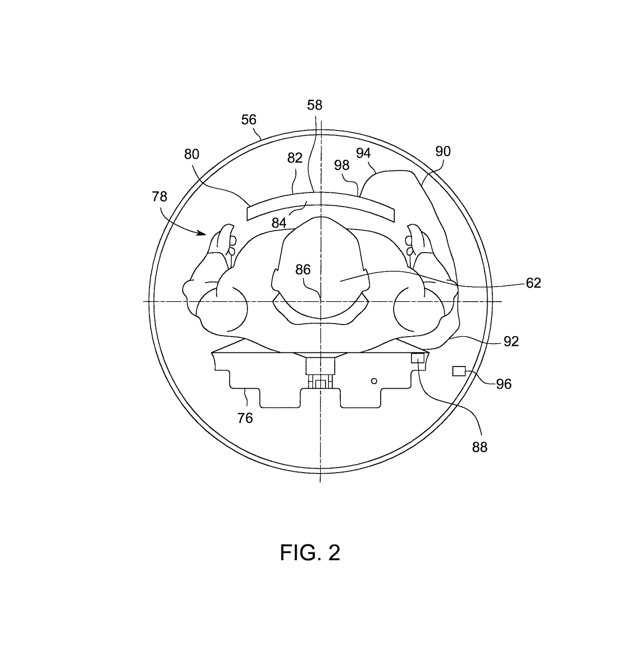
In a combined PET-MRI system, however, surface coils can potentially distort, i.e., attenuate, the emitted gamma rays prior to detection by the scintillators in the detector ring.
As a result, many PET-MRI systems are limited to using so called non-floating “rigid” surface coils, which are typically non-flexible and mounted / fixed to a known stationary location.
As a result, the location of such coils is neither fixed nor known with great precision.
Many floating surface coils are flexible, i.e., non-rigid, as well such that the coil shape may also not be known with great precision.

Method used


Image

  • System and method for attenuation correction of a surface coil in a PET-MRI system
  • System and method for attenuation correction of a surface coil in a PET-MRI system
  • System and method for attenuation correction of a surface coil in a PET-MRI system

Examples


Embodiment Construction

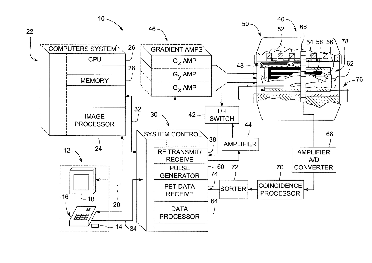
[0018]Reference will be made below in detail to exemplary embodiments of the invention, examples of which are illustrated in the accompanying drawings. Wherever possible, the same reference characters used throughout the drawings refer to the same or like parts, without duplicative description.

[0019]As used herein, the terms “substantially,”“generally,” and “about” indicate conditions within reasonably achievable manufacturing and assembly tolerances, relative to ideal desired conditions suitable for achieving the functional purpose of a component or assembly. The term “real-time,” as used herein, means a level of processing responsiveness that a user senses as sufficiently immediate or that enables the processor to keep up with an external process. As also used herein, the term “spatial location” means the location and / or orientation of an object in two-dimensional and / or three-dimensional space. As used herein, “electrically coupled”, “electrically connected”, “electrical communic...


PUM


Abstract

A PET-MRI system for imaging an object is provided. The PET-MRI system includes a magnetic resonance imaging sub-system, a positron emission tomography sub-system, an optical sensor, and a data processing controller. The magnetic resonance imaging sub-system includes a surface coil that acquires magnetic resonance signals from the object. The positron emission tomography sub-system acquires PET emissions from the object. The optical sensor detects at least one of a spatial location and a shape of the surface coil. The data processing controller communicates with the magnetic resonance imaging sub-system, the positron emission tomography sub-system, and the optical sensor, and utilizes at least one of the detected spatial location and the detected shape of the surface coil to correct the acquired PET emissions for attenuation.

Description

BACKGROUNDTechnical Field[0001]Embodiments of the invention relate generally to positron emission tomography (“PET”) and magnetic resonance imaging (“MRI” or “MR imaging”), and more specifically, to a system and method for attenuation correction of a surface coil in a combined PET-MRI system.Discussion of Art[0002]PET imaging involves the creation of tomographic images of positron emitting radionuclides in a subject of interest. A radionuclide-labeled agent is administered to a subject positioned within a detector ring. As the radionuclides decay, positively charged electrons known as “positrons” are emitted therefrom. As these positrons travel through the tissues of the subject, they lose kinetic energy and ultimately collide with an electron, resulting in mutual annihilation. The positron annihilation results in a pair of oppositely-directed gamma rays being emitted at approximately 511 keV, which are subsequently detected by scintillators in the detector ring. When struck by a ga...

Claims


Application Information

Patent Timeline
Patent Type & Authority Patents(United States)
IPC IPC(8): G01V3/00G01R33/48A61B6/00A61B6/03G01R33/341
CPCG01R33/481A61B6/037A61B6/5258A61B6/4417G01R33/341
Inventor LI, JIAQIBYSHENK, ANDREWGOSWAMI, CHINMOYWANG, TONGZHOU
Owner GENERAL ELECTRIC CO
Why Eureka
Eureka Blog
Learn More