
Tilting landing gear systems and methods

Active Publication Date: 2018-12-11
BLENDED WING AIRCRAFT INC
View PDF20 Cites 4 Cited by
  • Summary
  • Abstract
  • Description
  • Claims
  • Application Information

AI Technical Summary

Benefits of technology

The present disclosure is about a tilting, or rotating, landing gear system for aircraft. This system allows the aircraft to rotate around its center of gravity, regardless of where the landing gear is placed. The system reduces the effort needed to rotate the aircraft to the desired angle of attack for different procedures. It balances mechanical and hydraulic forces to reduce the aerodynamic forces required, and it can also include additional mechanical or hydraulic means in addition to the aircraft's own aerodynamic surfaces. The technical effect of this system is that it improves the efficiency and maneuverability of aircraft.

Problems solved by technology

While convenient from a packaging standpoint, the tube and wing configuration is not particularly efficient.
This is because the fuselage provides little or no lift, yet introduces substantial drag.
This results in a wing with higher lift, but proportionately higher drag.
Due to their unconventional shape, however, blended wing aircraft can present some challenges with regard to packaging.
In other words, because the shape of the fuselage is more irregular than a conventional tube-shaped fuselage, providing storage for cargo, equipment, passengers, and other components can be challenging.
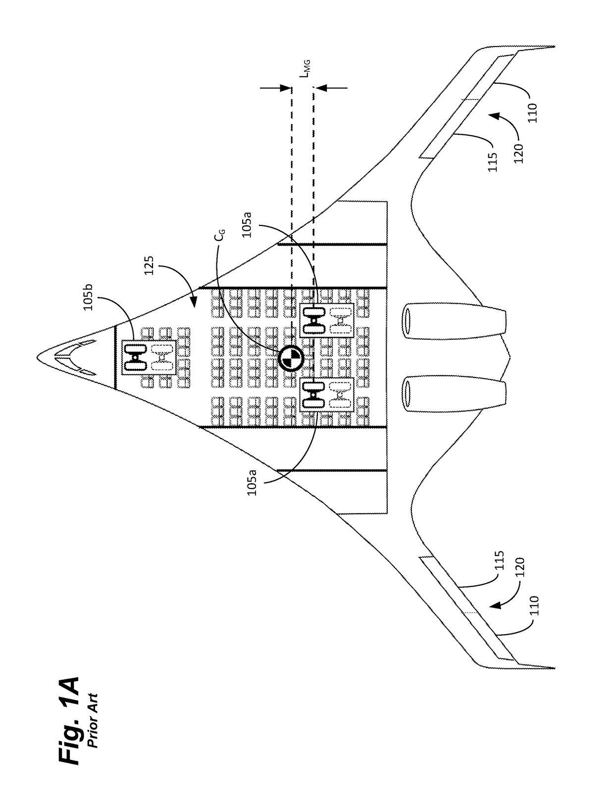
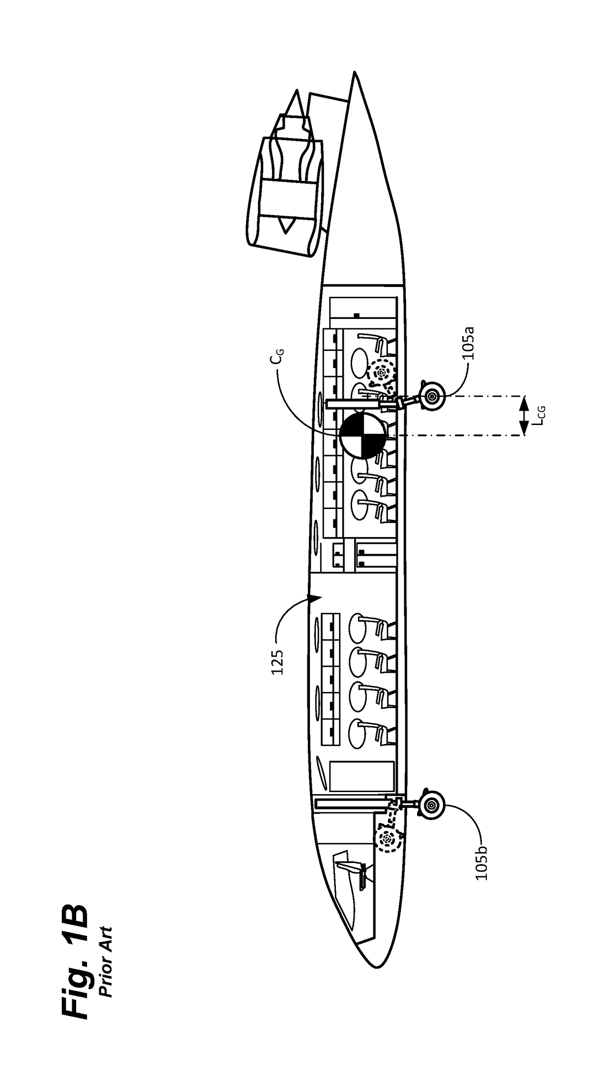
In particular, as shown in FIGS. 1A and 1B, finding a suitable place to stow the retracted landing gear 105 can be challenging.
In addition, the maximum width, or track, of the landing gear is limited by regulation to ensure landing gear / runway compatibility.
In a blended wing design, however, this unfortunately places the landing gear in the middle of the desired passenger compartment (on a single level aircraft) or in the middle of the cargo compartment (on a multi-level aircraft).
This reduces seating and / or cargo capacity and makes packaging, interior aesthetics, and utility more difficult, among other things.
Unfortunately, this places the main landing gear 105a at a substantial distance from the CG.
Thus, one problem—clearing the passenger and / or cargo compartment—has been traded for another—increasing takeoff distance or not being able to take off at all.

Method used


Image

  • Tilting landing gear systems and methods
  • Tilting landing gear systems and methods
  • Tilting landing gear systems and methods

Examples


example 1

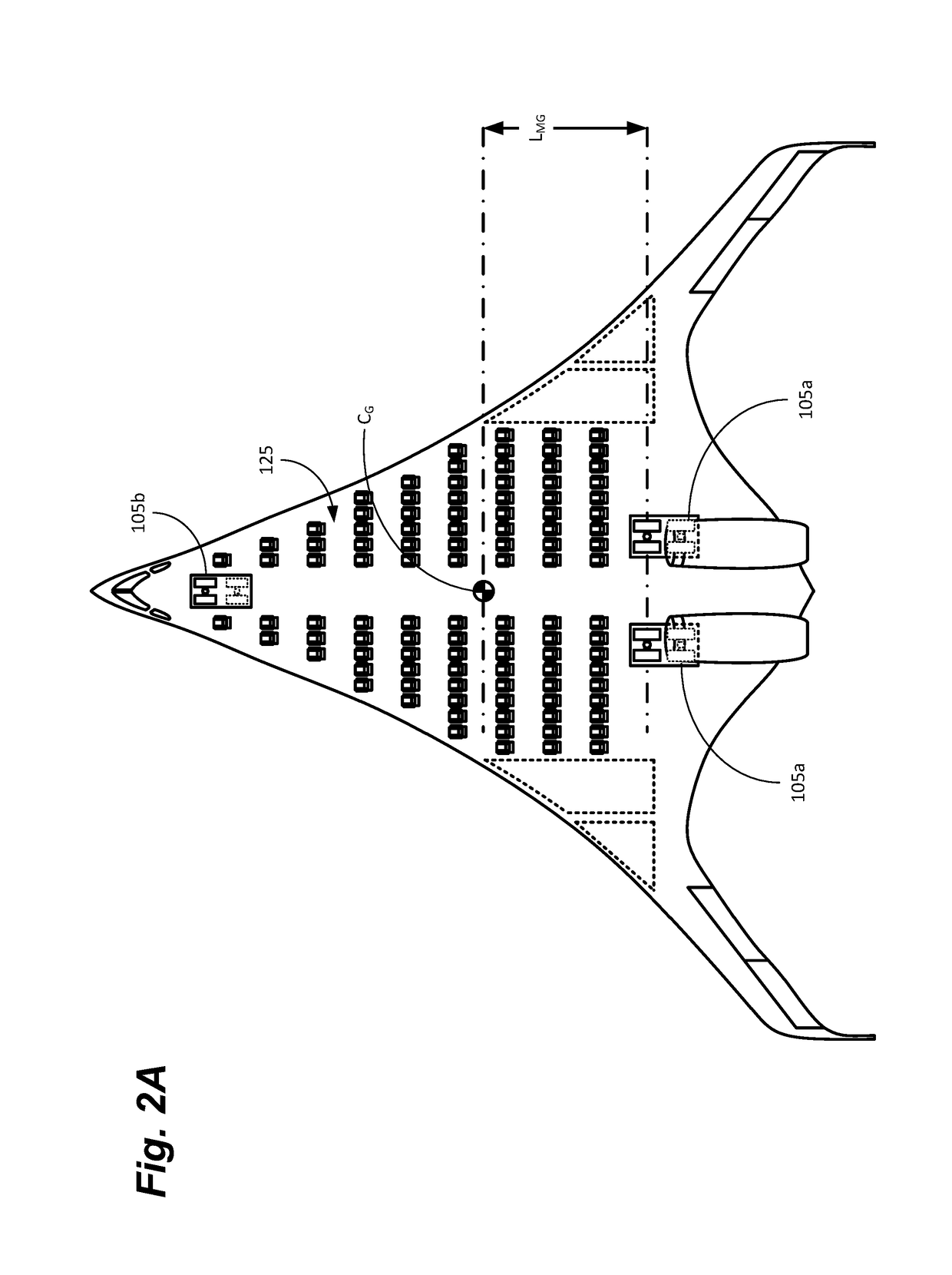
[0099]As discussed above, it is convenient to locate the main gear 305 behind the rear-spar where there is ample room to store the retracted main gear 305 in the “beaver-tail.” To allow the main gear 305 to be tens of feet behind the CG requires a new feature that works in concert with the nose gear 310. The location of the main gear 305 would normally prevent rotation because there isn't enough aerodynamic control moment to lift the plane's weight so far ahead of the main gear 305 axles.

[0100]To solve this, the main gear 305 and nose gear 310 are mounted to hydraulic cylinders 320 of approximately equal diameter for all three landing gears (one nose gear 310 and two main gear 305). The nose gear 310 and main gear 305 are plumbed together with a smaller hydraulic pipe 405 and share hydraulic fluid. The system can be passive so pumps 435 are not necessary, but may nonetheless be used. A hydraulic valve 410, between the nose gear 310 and main gear 305, can hydraulically lock the syste...


PUM


Abstract

Systems and methods for mechanically rotating an aircraft about its center-of-gravity (CG) are disclosed. The system can enable the rear, or main, landing gear to squat, while the nose landing gear raises to generate a positive angle of attack for the aircraft for takeoff or landing. The system can also enable the nose gear and main gear to return to a relatively level fuselage attitude for ground operations. The system can include one or more hydraulically linked hydraulic cylinders to control the overall height of the nose gear and the main gear. Because the hydraulic cylinders are linked, a change on the length of the nose cylinder generates a proportional, and opposite, change in the length of the main cylinder, and vice-versa. A method and control system for monitoring and controlling the relative positions of the nose gear and main gear is also disclosed.

Description

BACKGROUND[0001]Conventional aircraft consist essentially of a wing section and a fuselage. This so-called “tube and wing” configuration enables convenient packaging of passengers and cargo, but has certain drawbacks. In most cases, passengers are seated on a deck disposed approximately on the vertical centerline of the fuselage, while cargo is stowed beneath. This enables a relatively wide, flat floor for seats and separates cargo operations from passenger loading and unloading. Passengers can be loaded via one or more passenger doors, while cargo can be loaded from one or more cargo hatches on the underside or sides of the fuselage. This configuration also provides a relative constant fuselage cross section (less the nose and tail cones), enabling a substantially percentage of the available volume of the fuselage to be utilized.[0002]While convenient from a packaging standpoint, the tube and wing configuration is not particularly efficient. This is because the fuselage provides li...

Claims


Application Information

Patent Timeline
IPC IPC(8): B64C25/00
CPCB64C25/001B64C2025/008B64C25/14B64C39/10B64C2039/105
Inventor PAGE, MARK A.
Owner BLENDED WING AIRCRAFT INC
Learn More