
Zinc alloy plating method

a zinc alloy and plating technology, applied in the field of zinc alloy plating method, can solve the problems of reducing current efficiency, oxidative decomposition of amine-based chelating agent, deterioration of plating performance, etc., and achieves the effect of easy anode separation, prolonging the life and maintaining the performance of the zinc alloy plating bath

Active Publication Date: 2018-12-18
DISPOL CHEMICALS CO LTD
View PDF27 Cites 0 Cited by
  • Summary
  • Abstract
  • Description
  • Claims
  • Application Information

AI Technical Summary

Benefits of technology

The present invention is a plating method that uses an alkaline zinc alloy electroplating bath with an anion exchange membrane to prevent the movement of certain components (such as zinc ions and chelating agents) and maintain the performance of the bath. Additionally, the method allows for easy separation of the anode and cathode regions and easy management of the liquid level. This results in a cost-effective apparatus for achieving lifetime extension of the zinc alloy plating bath.

Problems solved by technology

However, when alkaline zinc-nickel alloy plating is performed, there arises a problem of oxidative decomposition of the amine-based chelating agent in the vicinity of the anode during current application.
Accordingly, when an alkaline zinc-nickel alloy plating liquid comes into contact with an anode, the amine-based chelating agent rapidly decomposes, resulting in deterioration in plating performance.
Accumulation of products of the decomposition causes many problems such as decrease in current efficiency, increase in bath voltage, decrease in plating thickness, decrease in nickel content in plated coating, narrowing of a permissible current density range for the plating, decrease in gloss, and increase in COD.
However, when an acidic liquid is used as the anolyte, it is necessary to use an expensive corrosion-resistant member, such as platinum-plated titanium, as the anode.
In addition, when the separation membrane is broken, there is a possibility of an accident in which the acidic solution on the anode side and the alkaline solution on the cathode side are mixed with each other to cause a rapid chemical reaction.
However, this method requires an additional apparatus, liquid management, and the like, which complicate the operations.
However, a test conducted by the present inventors has shown that the disclosed filtration membrane is incapable of preventing movement between the catholyte and the anolyte, and incapable of preventing decomposition of a chelating agent at the anode.

Method used


Image

  • Zinc alloy plating method
  • Zinc alloy plating method
  • Zinc alloy plating method

Examples


example 1

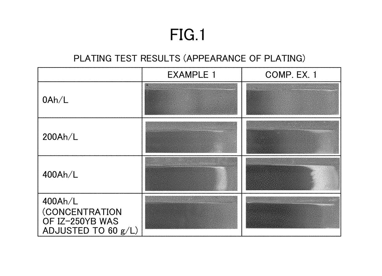
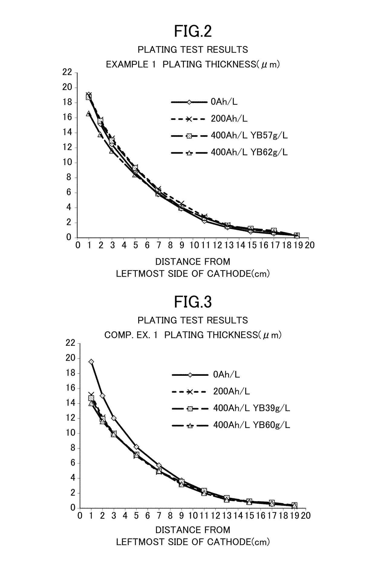
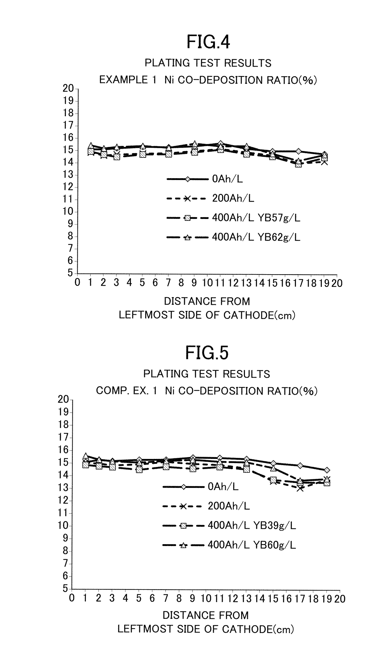
[0033]Zinc-nickel alloy plating was obtained as follows: Specifically, a cathode and an anode were separated from each other by an anion exchange membrane SELEMION (manufactured by Asahi Glass Co., Ltd., hydrocarbon-based quaternary ammonium base-type anion exchange membrane). An alkaline zinc-nickel alloy plating liquid shown below was used as a catholyte for a cathode chamber (500 mL), and a 130 g / L (3.3 mol / L) aqueous caustic soda solution was used as an anolyte for an anode chamber (50 mL). A current was applied at 400 Ah / L. The cathode current density was 4 A / dm2, the anode current density was 16 A / dm2, and the plating bath temperature was 25° C. The plating liquid was kept at 25° C. by cooling. An iron plate was used as the cathode, and a nickel plate was used as the anode. Note that the iron plate serving as the cathode was exchanged every 16 Ah / L during the current application. The zinc ion concentration in the catholyte was kept constant by immersing and dissolving zinc met...


PUM

PropertyMeasurementUnit
concentrationaaaaaaaaaa

Abstract

The present invention provides a zinc alloy electroplating method comprising applying a current through an alkaline zinc alloy electroplating bath comprising a cathode and an anode, wherein a cathode region including the cathode and an anode region including the anode are separated from each other by an anion exchange membrane, a catholyte contained in the cathode region is an alkaline zinc alloy plating liquid, and an anolyte contained in the anode region is an aqueous alkaline solution.

Description

RELATED APPLICATIONS[0001]This application is the U.S. National Stage of and claims the benefit of priority to International Patent Application Number PCT / JP2015 / 070876, filed Jul. 22, 2015. The entire contents of the foregoing are hereby incorporated herein by reference.[0002]The present invention relates to a zinc alloy plating method. Specifically, the present invention relates to a plating method by which a plating bath can be used for a long period with the performance of the plating bath being maintained with a simple anode separation apparatus in performing alkaline zinc alloy plating excellent in corrosion prevention characteristics on a steel member or the like.BACKGROUND ART[0003]Zinc alloy plating has a better corrosion resistance than zinc plating, and hence has been widely used for automobile components and the like. Among types of zinc alloy plating, especially alkaline zinc-nickel alloy plating has been used for fuel system components required to have high corrosion r...

Claims


Application Information

Patent Timeline
Patent Type & Authority Patents(United States)
IPC IPC(8): C25D3/56C25D17/00
CPCC25D17/002C25D3/565C25D3/56
Inventor NIIKURA, TOSHIHIROFUJIMORI, TAKAHIROHASHIMOTO, AKIRAINOUE, MANABU
Owner DISPOL CHEMICALS CO LTD
Learn More