Method of treating gas and gas treatment device

a gas treatment device and gas treatment technology, applied in the direction of chemistry apparatus and processes, separation processes, dispersed particle separation, etc., can solve the problems of secondary pollution, high cost of fuel, electricity and electrode dissipation, disadvantage and ineffectiveness of techniques

Active Publication Date: 2019-01-01
CHING JING PHOTONERGY TECH CO LTD
View PDF5 Cites 1 Cited by
  • Summary
  • Abstract
  • Description
  • Claims
  • Application Information

AI Technical Summary

Problems solved by technology

The techniques incur high costs in fuel, electricity, and electrode dissipation.
However, combustion, plasma cracking, and electrothermy, which are carried out at high temperature, entail cracking N2 into NOx again, thereby causing secondary pollution insidiously.
U.S. Pat. No. 5,206,002, U.S. Pat. No. 6,162,409, U.S. Pat. No. 6,649,132 and U.S. Pat. No. 7,303,735 disclose using ozone to treat N2O and NOx but require that oxidation should occur in the presence of ozone of a high concentration, i.e., 1.5 moles, to the detriment of applicability, because of cost-ineffectiveness.
China patent ZL03115442.5, Japan patent JP2000157621A, and Japan patent JP2001235201A disclose decomposing smelly gases, such as NH3 and H2S, with ultraviolet but prove disadvantageous and ineffective, because full-band ultraviolet lamps cannot endure an overly strong draft or an overly high concentration of smelly gas.
Therefore, the use of NH3 is likely to cause secondary pollution.
US20100108489 discloses that N2O gas in a UV chamber is cracked and repeatedly cycled to react with by-products so that NO gas is eventually produced; however, the production process takes at least tens of minutes and thus is inefficient, not to mention that the end product is still a nitrogen oxide.
None of the aforesaid patents discloses a solution pertaining to N2O (laughing gas).

Method used


Image

  • Method of treating gas and gas treatment device
  • Method of treating gas and gas treatment device
  • Method of treating gas and gas treatment device

Examples


Embodiment Construction

[0018]The present invention discloses a gas treatment method and a gas treatment device, wherein related basic principles, such as redox reactions of an intended gas, are well-known among persons skilled in the art and thus are not fully described below. The accompanying drawings, which depict structures related to the technical features of the present invention, are not and need not drawn to scale.

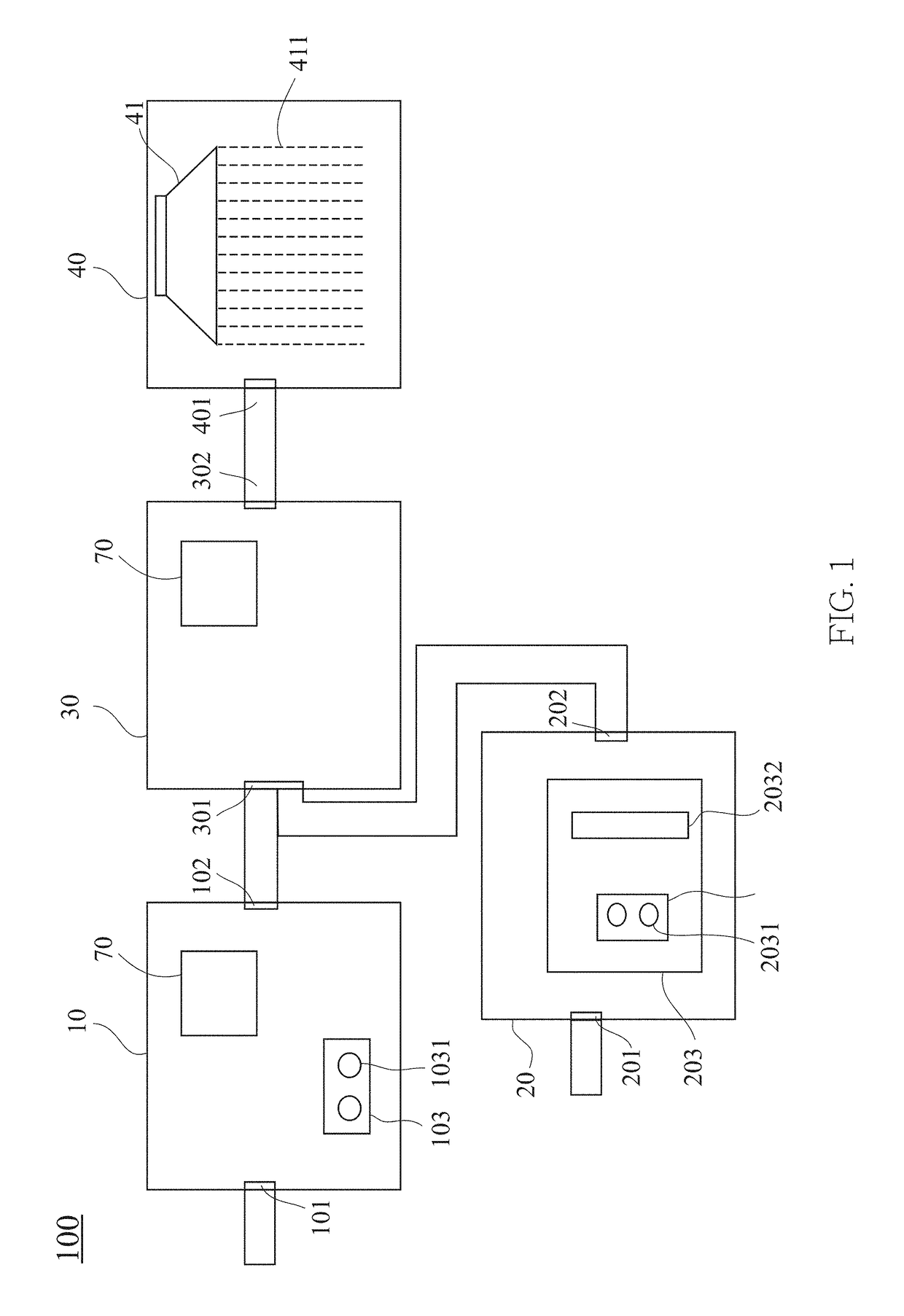
[0019]The present invention provides a gas treatment device 100 for treating a gas comprising a nitrous oxide (N2O). The gas treatment device 100 comprises a plurality of chambers in communication with each other, namely a first chamber 10, a second chamber 20, a third chamber 30 and a fourth chamber 40. Operation of the chambers is described below.

[0020]The first chamber 10 comprises a first inlet 101, a first outlet 102 and a first energy supply system 103. The gas, which comprises noxious gases, enters the first chamber 10 through the first inlet 101. The gas, such as sulfur oxides (SO...


PUM

PropertyMeasurementUnit
wavelengthaaaaaaaaaa
Reynolds numberaaaaaaaaaa

Abstract

Method of treating gas and gas treatment device, the gas treatment device comprising: a first chamber, comprising a first inlet, a first outlet and a first energy supply system, allowing the gas to enter the first chamber through the first inlet; a second chamber comprising a second outlet and a second energy supply system; a third chamber comprising a third inlet in communication with the first outlet and the second outlet; and a fourth chamber comprising a fourth inlet and a scrubbing system containing a solvent comprising water molecules (H2O), wherein the third outlet of the third chamber is in communication with the fourth inlet of the fourth chamber.

Description

BACKGROUND OF THE INVENTIONField of the Invention[0001]The present invention relates to methods of treating a gas and gas treatment devices and, more particularly, to a method of treating a gas and a gas treatment device with a view to purifying the gas by cracking the gas and ozone separately and then allowing the products to mix and react with each other.Description of the Prior Art[0002]Nitrous oxide (N2O) accounts for destruction of the ozone layer, because N2O has an enormous ability to absorb vacuum ultraviolet (VUV) and decompose into nitrogen gas (N2) and oxygen atoms (O). Then, the oxygen atoms (O) react with ozone (O3) to produce oxygen gas (O2), thereby depleting ozone (O3). The aforesaid process is expressed by chemical equations as follows:N2O+hv→N2+OO+O3→2O2 [0003]Semiconductor fabs, which often have strict requirements for greenhouse gas emissions and standards, endeavor to develop techniques of eliminating N2O end gas and reducing NOx, for example, combustion, plasma...

Claims


Application Information

Patent Timeline
Patent Type & Authority Patents(United States)
IPC IPC(8): B01D53/00B01D53/34B01D53/50B01D53/14B01L5/02B01D53/56B01L7/00B01D53/32
CPCB01D53/1493B01D53/007B01D53/32B01D53/56B01D2259/804B01D2252/103B01D2257/402B01D2258/0216B01D2258/0283B01D2251/104B01D53/005B01D53/76B01D2258/06Y02C20/10
Inventor LI, TA-CHINGCHEN, TSUI-MIN
Owner CHING JING PHOTONERGY TECH CO LTD
Why Eureka
Try Eureka