Cutter holder for a tunnel boring machine and an associated cutting set

a cutting set and tunnel boring machine technology, applied in the direction of drilling accessories, underground chambers, mining structures, etc., can solve the problems of reducing the service life of the cutter, affecting the cutting accuracy of the cutter, etc., so as to reduce the impact of the cutter, and suppress the effect of human intervention

Active Publication Date: 2019-01-08
BOUYGUES TRAVAUX PUBLICS SA
View PDF8 Cites 0 Cited by
  • Summary
  • Abstract
  • Description
  • Claims
  • Application Information

AI Technical Summary

Benefits of technology

[0013]One purpose of the present invention is thus to provide a cutter holder and a cutting set for a tunnel boring machine comprising a tunnel boring machine roller cutter and an associated cutter holder, capable of supporting the very harsh environment of the roller cutters, in particular the high pressure and vibrations generated by rolling the roller cutter on the cutting face, and which further allow any human intervention upon replacing one roller cutter to be reduced, or even suppressed.
[0014]Another purpose of the invention is to provide a method for replacing a roller cutter of such a cutting set, as well as a handling device for the roller cutter adapted to implement this method, by enabling in particular any loss of parts to be avoided.
[0027]the side wedges and the centre wedge comprise associated pressing faces, configured to be engaged when the side wedges are in the clamping position in order to withstand strains passing through the clamping sets and provide a stable state to said clamping sets,

Problems solved by technology

The problem of changing the roller cutters occurs particularly in the case of a confined face tunnel boring machine, because access to the cutting head and to the roller cutter attachments (wedges, screws, etc.) is difficult and the working environment is under hyperbaric conditions.
The procedure for changing a roller cutter often demands the exertion of considerable forces for loosening the used roller cutter from its housing, due to jams and the absence of guidance for the roller cutter, which is poorly compatible with work under hyperbaric conditions.
Before inserting the new roller cutter in its housing, it must be properly positioned, which requires a painstaking manual intervention.
It will be understood therefore that this procedure is long and tedious for the operators.
However, in use, the roller cutter undergoes very high pressure and vibration stresses which might move out the bayonet.
Indeed, it is difficult to apply a prestressed strain enough to resist the vibrations of the roller cutter in a hard field.

Method used


Image

  • Cutter holder for a tunnel boring machine and an associated cutting set
  • Cutter holder for a tunnel boring machine and an associated cutting set
  • Cutter holder for a tunnel boring machine and an associated cutting set

Examples


Embodiment Construction

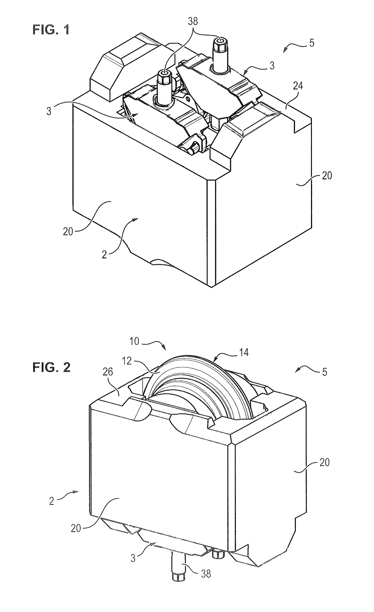
[0059]A cutting assembly 5 comprises a cutter holder 1 for a tunnel boring machine and a roller cutter 10 housed in the holder 1.

[0060]A roller cutter 10 presents, in a known manner, the general shape of a disk comprising two side faces connected by a substantially circular section 14. During rotation of the head of the tunnel boring machine and under the influence of thrust, the section 14 of the roller cutter 10 rolls over the cutting face and chips out the rock, forming scale-like plates.

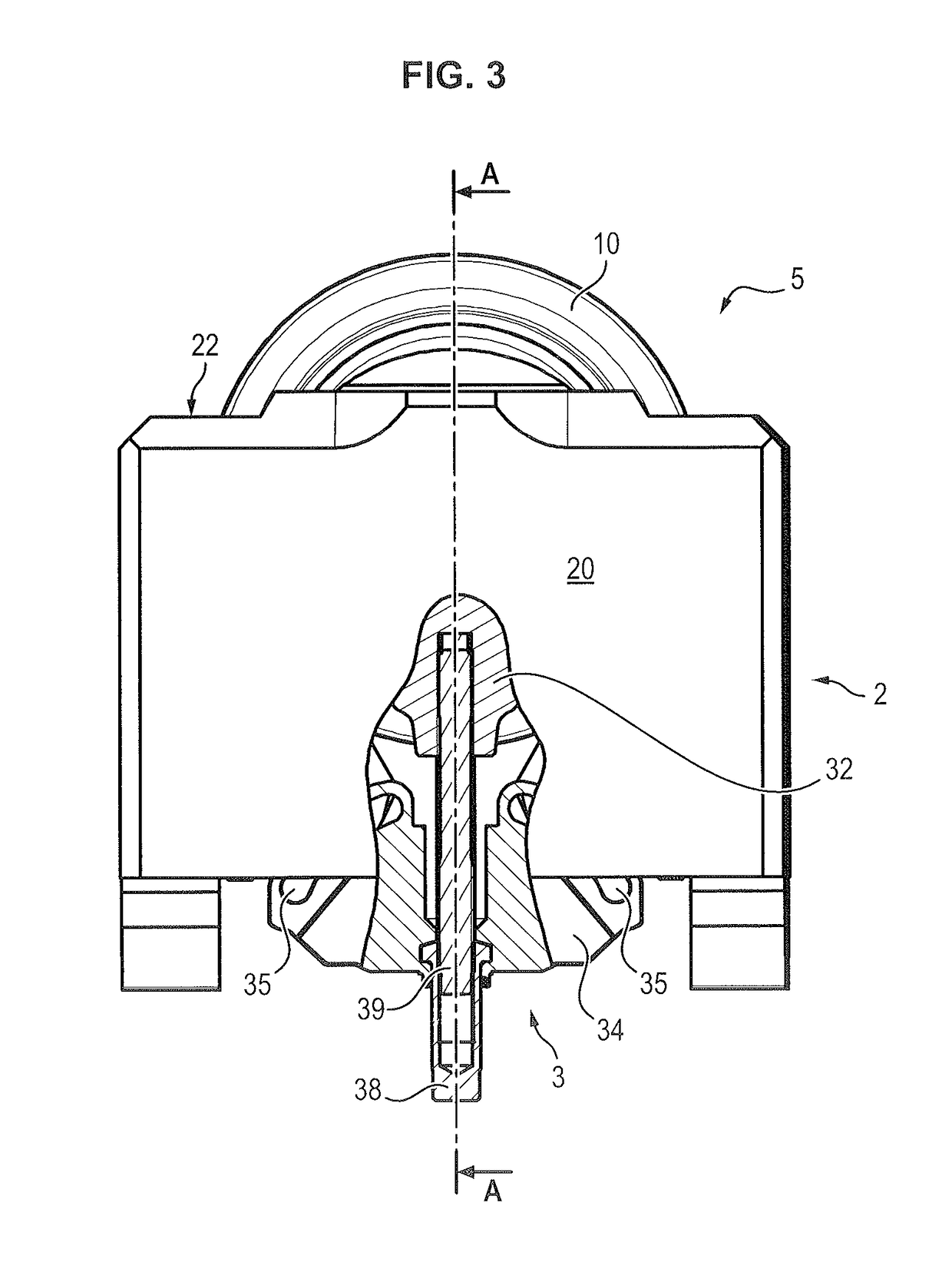
[0061]The roller cutter 10 is mounted in a holder 1 so as to be free to move in rotation around its rotation axis X.

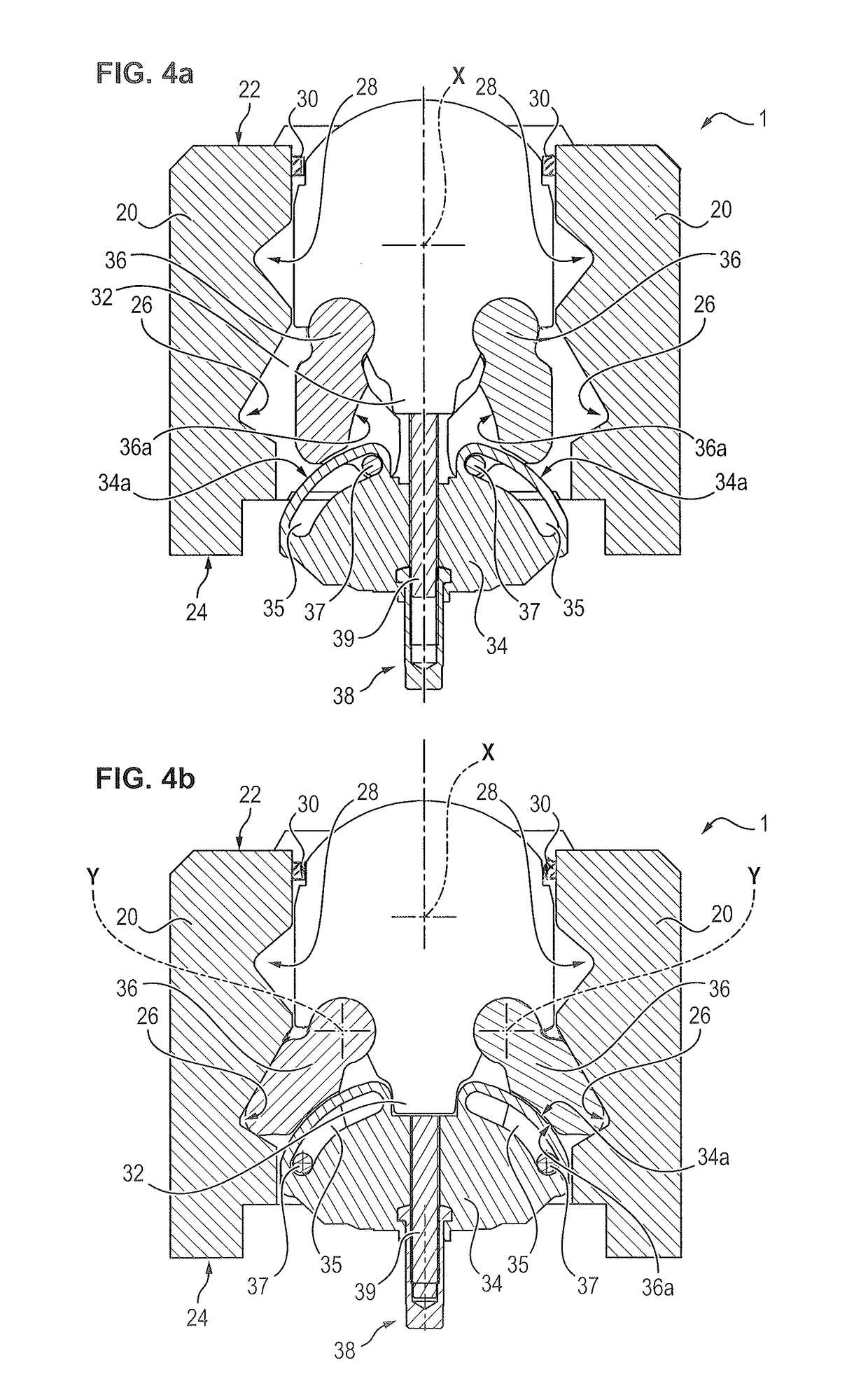
[0062]For this purpose, the holder 1 comprises a housing 2, designed to be fastened onto a tunnel boring machine shield and two clamping assemblies 3 mounted on either side of the roller cutter 10 in a removable manner in the housing 2 to clamp the roller cutter 10 inside said housing 2.

[0063]The housing 2 comprises side walls 20 connected by a front face 22 and a rear face 24 and t...


PUM


Abstract

The invention relates to a cutter holder (1) for a tunnel boring machine, comprising:a housing (2) comprising two cavities (26) formed in opposite walls (20), andtwo clamping sets (3), configured to be removably mounted on either side of the roller cutter (10) in the housing (2), and each comprising:a base plate (32), anda center wedge (34), movably mounted on the base plate (32),two side wedges (36), hinged between the base plate (32) and the center wedge (34) between a retracted position and a clamping position, wherein the side wedges (36) transversely swing and enter into the cavity (26) facing the housing (2).

Description

FIELD OF THE INVENTION[0001]The invention relates to a cutting set for a tunnel boring machine including a tunnel boring machine roller cutter, a method for replacing a tunnel boring machine roller cutter on the cutting head of a tunnel boring machine suitable for such a cutter holder as well as a handling device for the holder cutter.TECHNOLOGICAL BACKGROUND[0002]Tunnel digging machines or tunnel boring machines are known, which comprise a movable structure having large dimensions which is called a shield, having a substantially circular cross-section the diameter of which corresponds to the diameter of the tunnel the digging of which is made.[0003]A roller cutter, or cutting disk, is a cutting tool freely revolving around a shaft attached to the cutting head of a tunnel boring machine. During rotation of the head and under the influence of thrust, the roller cutter rolls over the cutting face and chips out the rock in the form of scale-like plates.[0004]Thus, the cutting head incl...

Claims


Application Information

Patent Timeline
Patent Type & Authority Patents(United States)
IPC IPC(8): E21D9/10E21B10/20
CPCE21D9/1006E21D9/104E21D9/10E21B10/20E21D9/11E21D13/00
Inventor LIOTARD, PHILIPPEROBERT, PATRICE
Owner BOUYGUES TRAVAUX PUBLICS SA
Why Eureka
Try Eureka