
Circularly polarized illumination and detection for depth sensing

a circular polarization illumination and depth sensing technology, applied in the field of depth sensing, can solve the problems of low signal-to-noise ratio and large depth errors in depth maps obtained in these environments

Active Publication Date: 2019-01-15
META PLATFORMS TECH LLC
View PDF4 Cites 20 Cited by
  • Summary
  • Abstract
  • Description
  • Claims
  • Application Information

AI Technical Summary

Benefits of technology

The patent describes a depth camera assembly (DCA) that uses polarized light to determine depth information about objects in a local area. The DCA includes a polarized light generator, an imaging device, and a controller. The polarized light generator illuminates the area with polarized light, and the imaging device captures the reflected polarized light from the objects. The reflected light is then filtered to reduce ambient light and detect the portion of the light with the same polarization as the reflected light. The depth information about the objects is determined based on the detected portion of the reflected light. The DCA can be integrated into a head-mounted display (HMD) for use in virtual or augmented reality applications.

Problems solved by technology

The problem related to the depth sensing methods based on structured light illumination and time-of-flight is related to designing a compact and efficient depth camera that can produce quality depth maps in both indoor and outdoor environments where background ambient light can strongly interfere depth measurements.
The depth map obtained in these environments typically have large depth errors and a low level of signal-to-noise ratio (SNR) due to the strong background ambient light.

Method used


Image

  • Circularly polarized illumination and detection for depth sensing
  • Circularly polarized illumination and detection for depth sensing
  • Circularly polarized illumination and detection for depth sensing

Examples


Embodiment Construction

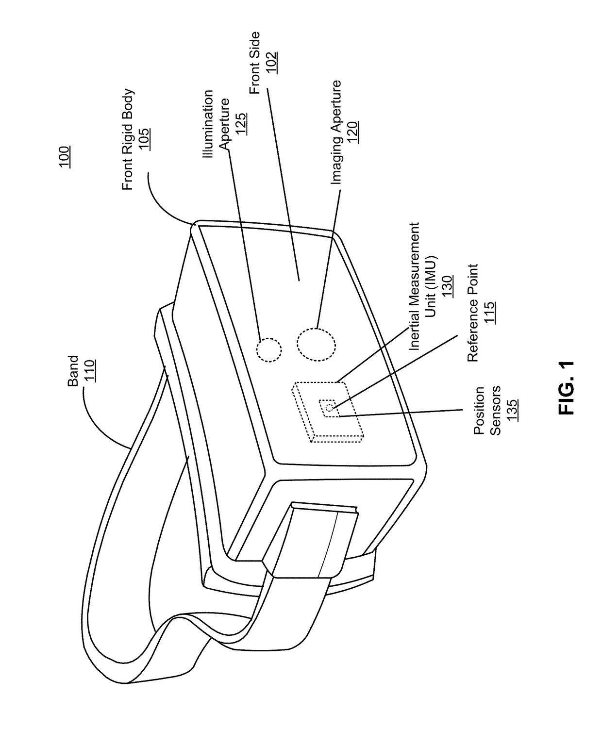
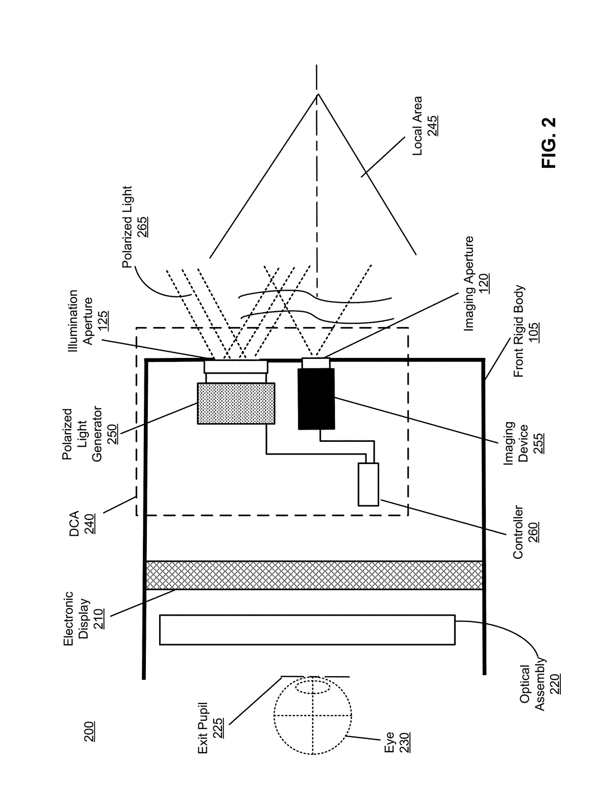
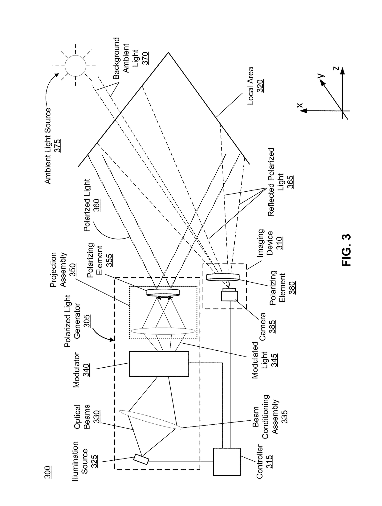
[0013]A depth camera assembly (DCA) for determining depth information of objects in a local area surrounding some or all of the DCA. The DCA includes a light source, a camera and a controller. The light source includes a laser source and a modulator that generates light that is, e.g., circularly polarized at a first handedness, using light emitted from the laser source. The light source also projects the generated circularly polarized light into the local area. The camera captures portions of the circularly polarized light reflected from the objects in the local area. The camera is configured as a polarization sensitive camera that detects the reflected circularly polarized light of a second handedness that may be opposite the first handedness. The use of polarized light increases a signal-to-noise ratio (SNR) as an intensity of un-polarized background ambient light can be efficiently reduced at the polarization sensitive camera. The controller determines depth information based on ...


PUM


Abstract

A depth camera assembly (DCA) for depth sensing of a local area. The DCA includes a polarized light generator, an imaging device, and a controller. The polarized light generator modulates one or more optical beams emitted from an illumination source to generate modulated light, and projects the modulated light into the local area as polarized light having a first polarization. The imaging device receives light from the local area, the received light including ambient light and a portion of the polarized light reflected from the local area. The imaging device reduces an intensity of the received light having polarization different from a second polarization to generate filtered light substantially composed of light of the second polarization, and detects the portion of the polarized light having the second polarization using the filtered light. The controller determines depth information for the local area based on the detected portion of the polarized light.

Description

BACKGROUND[0001]The present disclosure generally relates to depth sensing, and specifically relates to circularly polarized illumination and detection for depth sensing.[0002]To achieve compelling augmented reality (AR) and virtual reality (VR) user experiences, it is desired to create a depth sensing device that can determine a dense three-dimensional mapping in both indoor and outdoor surroundings. A depth camera usually involves structured light illumination, which is a triangulation technique that makes use of an active illumination source to project known patterns into a scene. The depth camera typically utilizes a two-dimensional pixel array detector to measure and record light back-scattered from one or more objects in the scene. Other methods for depth sensing are based on a time-of-flight technique, which measures a round trip travel time-of-light projected into the scene and returning to pixels on a sensor array. The problem related to the depth sensing methods based on st...

Claims


Application Information

Patent Timeline
IPC IPC(8): G06T7/521G02B26/08H04N5/225G02B5/18G02B5/30G06F1/16G02B26/10
CPCG06T7/521G02B5/1828G02B26/0808H04N5/2256G06T2207/10028G06F1/163G06F1/1637G06F1/1686G02B5/3025G02B26/10G02B27/28H04N5/2226G06T2207/10152G01B11/24G01S7/499G06F3/011G01S17/894H04N23/56G01B11/25G01S17/06
Inventor CHAO, QINGHALL, MICHAEL
Owner META PLATFORMS TECH LLC
Learn More