
Thermally conductive interface composition and use thereof

a technology of thermal interface and composition, applied in the direction of basic electric elements, chemistry apparatus and processes, and modifications by conduction heat transfer, can solve the problems of increasing the demand for effective heat dissipation methods, thermal interface material experiences tremendous mechanical stress, and the cross-link density of the present composition is increased

Inactive Publication Date: 2019-01-29
WU JIALI +1
View PDF10 Cites 0 Cited by
  • Summary
  • Abstract
  • Description
  • Claims
  • Application Information

AI Technical Summary

Benefits of technology

[0007]It is accordingly an object of this composition invention to provide a gel-forming silicone composition excelling thermal conductivity with low viscosity, low modulus, flexibility, and not prone to adhesive or cohesive fracture. To achieve this goal, the present invention comprises a curable silicone based composition with thermally conductive filler loading. Before cure, the materials have properties similar to grease or paste, they have high thermal conductivity, low surface tension, and conform well onto surface irregularities upon dispense and assembly, which contributes to thermal contact resistance minimization. After cure, the crosslink reaction provides cohesive strength to circumvent the pump-out issues exhibited by grease or paste during temperature cycling. Their modulus is low that the material can dissipate thermal stress and prevent interfacial delamination or cohesive fracture.
[0023]In present invention, a mixture of thermally conductive filler composition is mixed with organic vehicle to enhance the thermal conductivity. To lower the relative viscosity of the mixture at the same filler loading percent. Fillers in spherical or cubic octahedral shape are preferred. The average size of large particle must be selected in a range that balances bonding interface thickness and thermal conductivity effectiveness for an interface material. Addition of small particles are to increase the particle packing density, so as to the thermal conductivity. In addition, the effect of adding nanoparticle is to disentangle polymeric chain and reduce contact interface between micro size particles and polymer liquid matrix, which leads to further increasing of filler loading in thermally conductive mixtures with marginal viscosity budget.
[0031]A reaction inhibitor for suppressing catalytic activity of component (E) at room temperature for thereby extending the shelf life and pot life of the thermally conductive interface material of present invention. Example of reaction inhibitor are acetylenic alcohols such as 3, 5-dimethyl-1-hexyn-3-ol, 2-methyl-3-hexyn-2-ol, 3-methyl-3-penetene-1-yne, 1-ethynylcyclohexanol, or methylvinylsiloxane cyclic compounds, or an organic nitrogen compounds. On use, the inhibitor may be diluted with organic solvent such as toluene, xylene or isopropyl alcohol in order to improve its dispersion in the silicone resin.
[0034]Component (F) has a potential of increasing cross-link density of the present composition. The desirable amount of hydroxyl group-containing organopolysiloxane is in 0.0001-5% of the weight of component (A) and (B) combined.

Problems solved by technology

Due to the relentless pursuit of computing performance and functionality, improving heat dissipation becomes one of the central challenge issues.
As a result, the high-end microelectronic components are experiencing ever growing total power dissipation and heat fluxes, which increase the demand for effective means of heat dissipation.
For organic electronic component packages, thermal interface material experiences tremendous mechanical stress during module assembly processes.
However, due to the further increase in power assumption, which results in high heat density on electronic component, a sufficient heat dissipation effect cannot be obtained using traditional thermally conductive material.
Furthermore, Insufficient mechanical compliance of cured material could result in cohesive fracture introduced thermal failure.

Method used


Image

  • Thermally conductive interface composition and use thereof
  • Thermally conductive interface composition and use thereof

Examples


Embodiment Construction

[0045]The raw materials for examples 1-6 were uniformly mixed according to the amounts as given in table I.

[0046]The compounds used as component (A) are A-1 and A-2. They are linear alkenyl-terminated organopolysiloxane represented on the average by the formula;

(ViMe2SiO0.5)1.2(Me2SiO)138.2  A-1

(ViMe2SiO0.5)1.3(Me2SiO)187.3(Me3SiO0.5)1.5(MeSiO1.5)2.0.  A-2

wherein Me stands for the methyl group and Vi stands for the vinyl group. A-1 has vinyl group 0.43 mol %, viscosity 280 cP. A-2 has vinyl group mole 0.45% and viscosity 310 cP.

[0047]The compounds used as component (B) are B-1 to B-2. They are branched alkenyl-group containing organopolysiloxane represented on the average by formula:

(Me3SiO0.5)0.75(MeViSiO)1.5(Me2SiO)40  B-1

(Me3SiO0.5)1.0(MeViSiO)1.7(Me2SiO)79  B-2

wherein B-1 having vinyl group 0.30 mol %, viscosity 450 cP. B-2 having vinyl group 0.35 mole % and viscosity 550 cP.

[0048]The thermally conductive fillers used as component C are diamond, aluminum, and alumina. C-1 is dia...


PUM

PropertyMeasurementUnit
mol %aaaaaaaaaa
sizeaaaaaaaaaa
sizeaaaaaaaaaa

Abstract

A thermally conductive interface composition is interposed between a heat generating component and a heat dissipating component. To meet escalated heat dissipation for performance demanding devices, a thermally conductive interface composition comprises (A) A linear alkenyl organopolysiloxane containing a silicon-bonded alkenyl-terminated group or groups, (B) A branched alkenyl organopolysiloxane containing at least two silicon-bonded alkenyl groups, (C) thermally conductive fillers in a ternary particle size mixture, (D) An organohydrogenpolysiloxane containing at least two Si—H terminated groups, (E) An addition reaction catalyst, (F) A hydroxy group-containing siloxane, (G) Alkoxy group-containing siloxanes.

Description

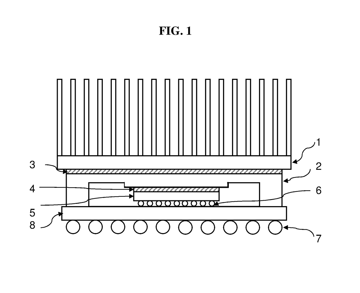
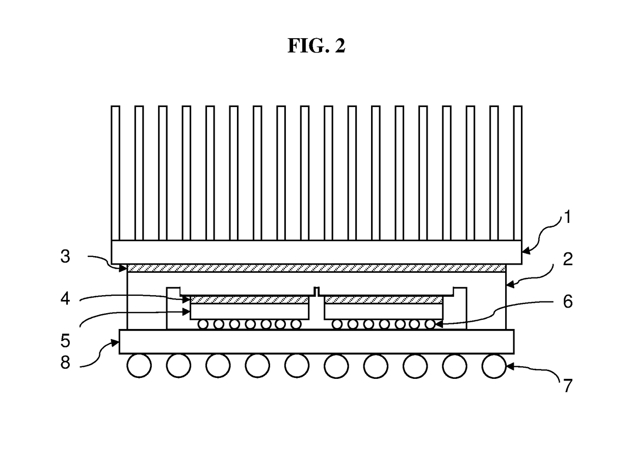
BACKGROUND[0001]Electronic components such as multi-core processor generate heat during operation and the heat needs to be dissipated efficiently for the device to function properly. A common expedient for this purpose is to transfer heat from electronic component (e.g. FIG. 1-5, FIG. 2-5) to a heat spreader (e.g. FIG. 1-2, FIG. 2-2), and then to heat sink (e.g. FIG. 1-1, FIG. 2-1) through an integrated thermal path, which was established by attaching a heat spreader directly on the electronic component, and then a heat sink on the heat spreader using thermally conductive interface materials (FIG. 1-3, 4; FIG. 2-3, 4). Effectiveness of heat dissipation is dominated by thermal conductivity and mechanical integrity of the interface materials.[0002]Due to the relentless pursuit of computing performance and functionality, improving heat dissipation becomes one of the central challenge issues. The recent trend in microprocessor architecture has been to increase the number of transistors,...

Claims


Application Information

Patent Timeline
Patent Type & Authority Patents(United States)
IPC IPC(8): C09K5/14C08L83/04C08K3/20C08K3/04H05K7/20C08K3/08C08K3/22C08K5/5415
CPCC09K5/14C08K3/04C08K3/20C08L83/04H05K7/2039C08K5/5415C08K2003/0812C08K2201/005C08K2003/2227H01L23/3737H01L23/42H01L2224/16225H01L2224/73253H01L2924/15311H01L2924/16152C08G77/12C08G77/16C08G77/18C08G77/20C08K2201/001C08L83/00C08K5/56C08K3/22
Inventor WU, JIALISHAN, KELLSIESHAN, LEI
Owner WU JIALI
Learn More