

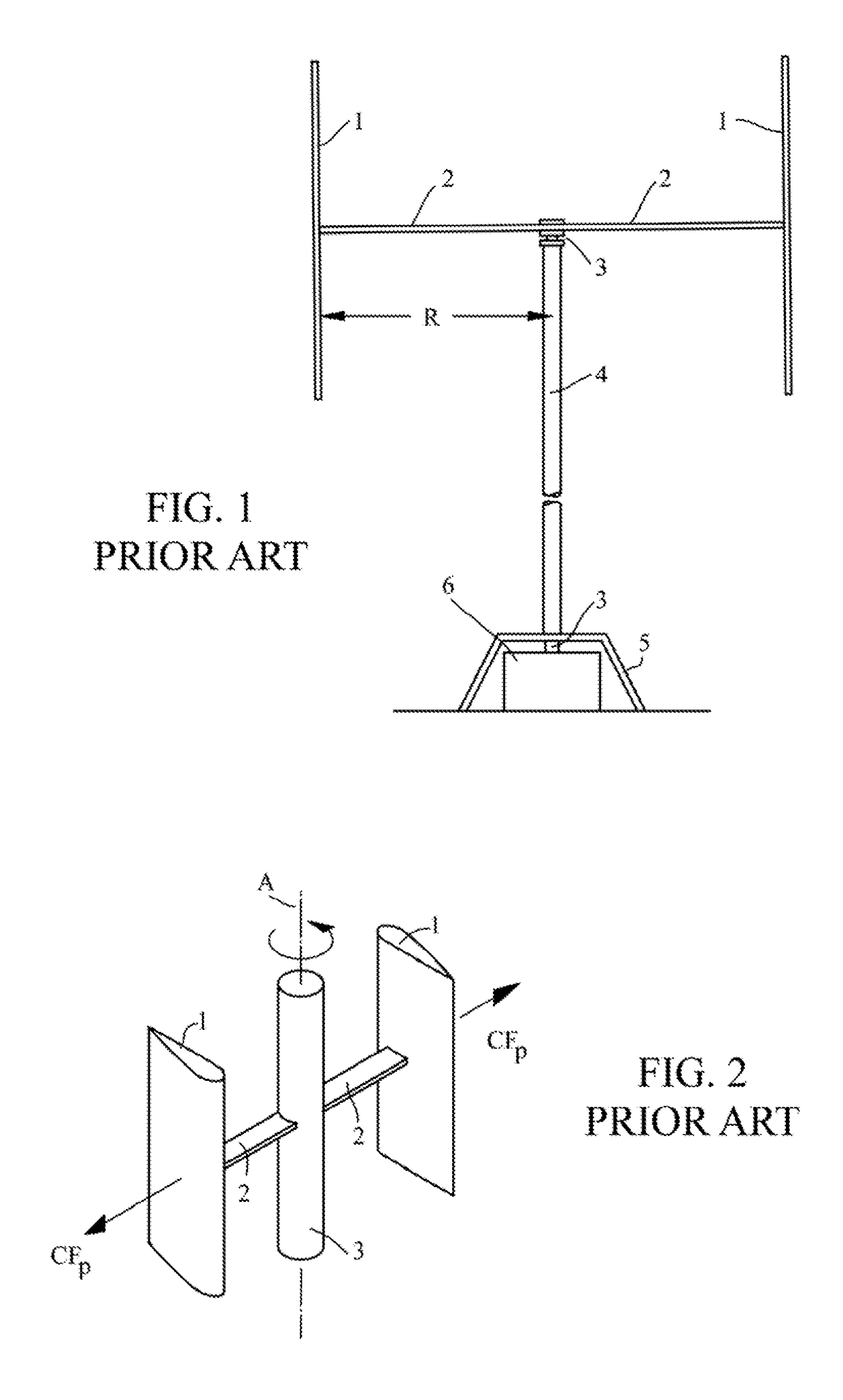
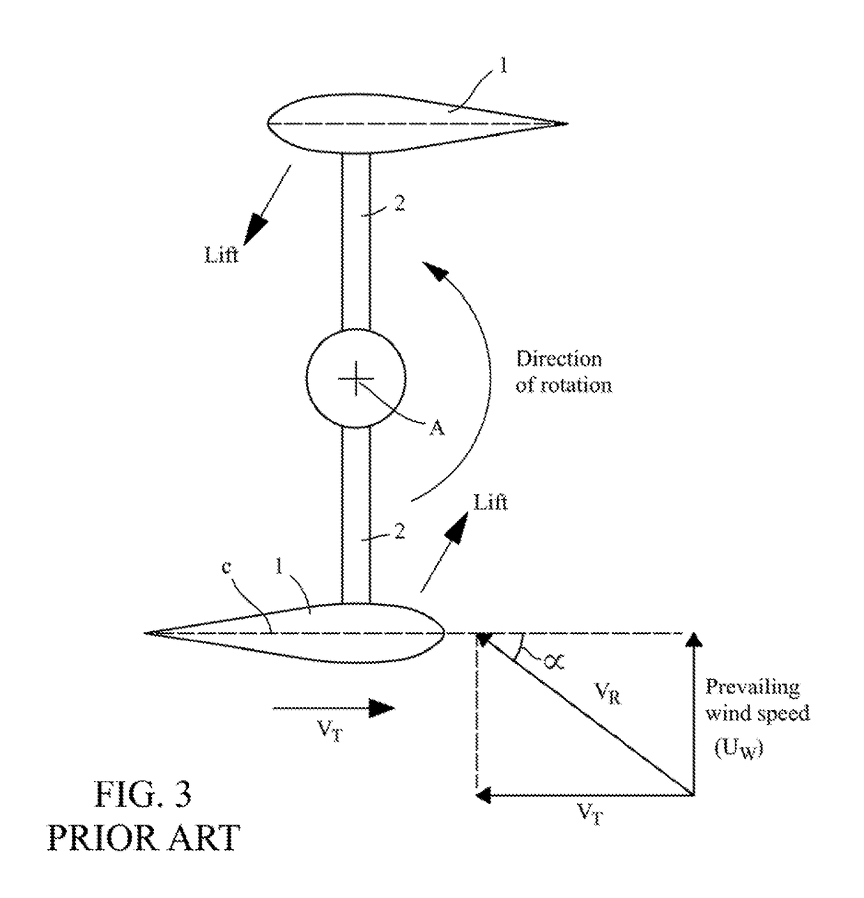
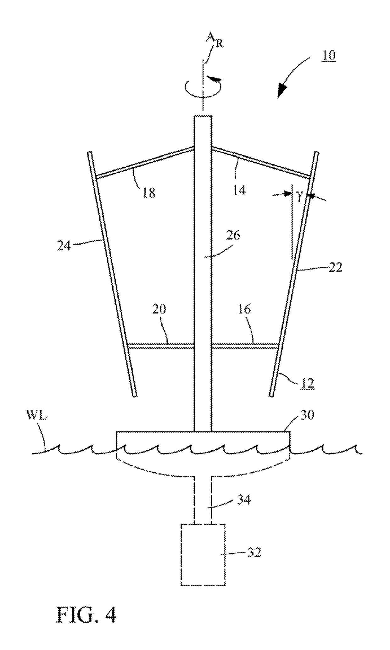
Lift-driven wind turbine with force canceling blade configuration
a technology of lift-driven wind turbines and blade configurations, which is applied in the direction of machines/engines, renewable energy generation, greenhouse gas reduction, etc., can solve the problems of aggravated fatigue issues, subject to regular, periodic stresses, and subject to fatigue, so as to reduce radial loads and reduce stresses , the effect of minimizing structural cos
- Summary
- Abstract
- Description
- Claims
- Application Information
AI Technical Summary
Benefits of technology
Problems solved by technology
Method used
Image

Examples
Embodiment Construction
[0031]The detailed description that follows is intended to provide specific examples of particular embodiments illustrating various ways of implementing the claimed subject matter. It is written to take into account the level of knowledge of one of ordinary skill in the art to which the claimed subject matter pertains. Accordingly, certain details may be omitted as being unnecessary for enabling such a person to realize the embodiments described herein.
[0032]In general, terms used throughout have the ordinary and customary meaning that would be ascribed to them by one of ordinary skill in the art. However, some of the terms used in the description herein will be explicitly defined and that definition is meant to apply throughout. For example, the term is “substantially” is sometimes used to indicate a degree of similarity of one property or parameter to another. This means that the properties or parameters are sufficiently similar in value to achieve the purpose ascribed to them in ...
PUM
 Abstract
Description
Claims
Application Information