Method and apparatus for high speed clock transmission

a transmission circuit and high-speed clock technology, applied in the field of clock transmission, can solve the problems of weak signal on the receiving end, difficult clock transmission, etc., and achieve the effects of boosting the output and reducing the input impedance of the current buffer

Active Publication Date: 2019-03-05
REALTEK SEMICON CORP
View PDF3 Cites 7 Cited by
  • Summary
  • Abstract
  • Description
  • Claims
  • Application Information

AI Technical Summary

Benefits of technology

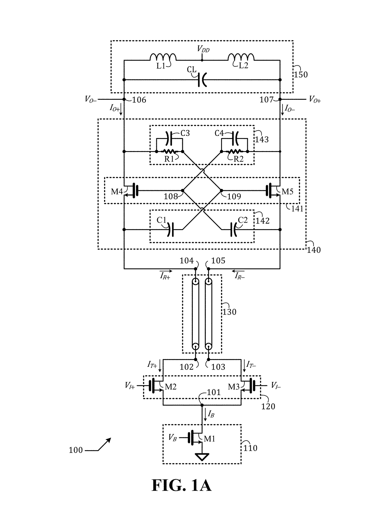
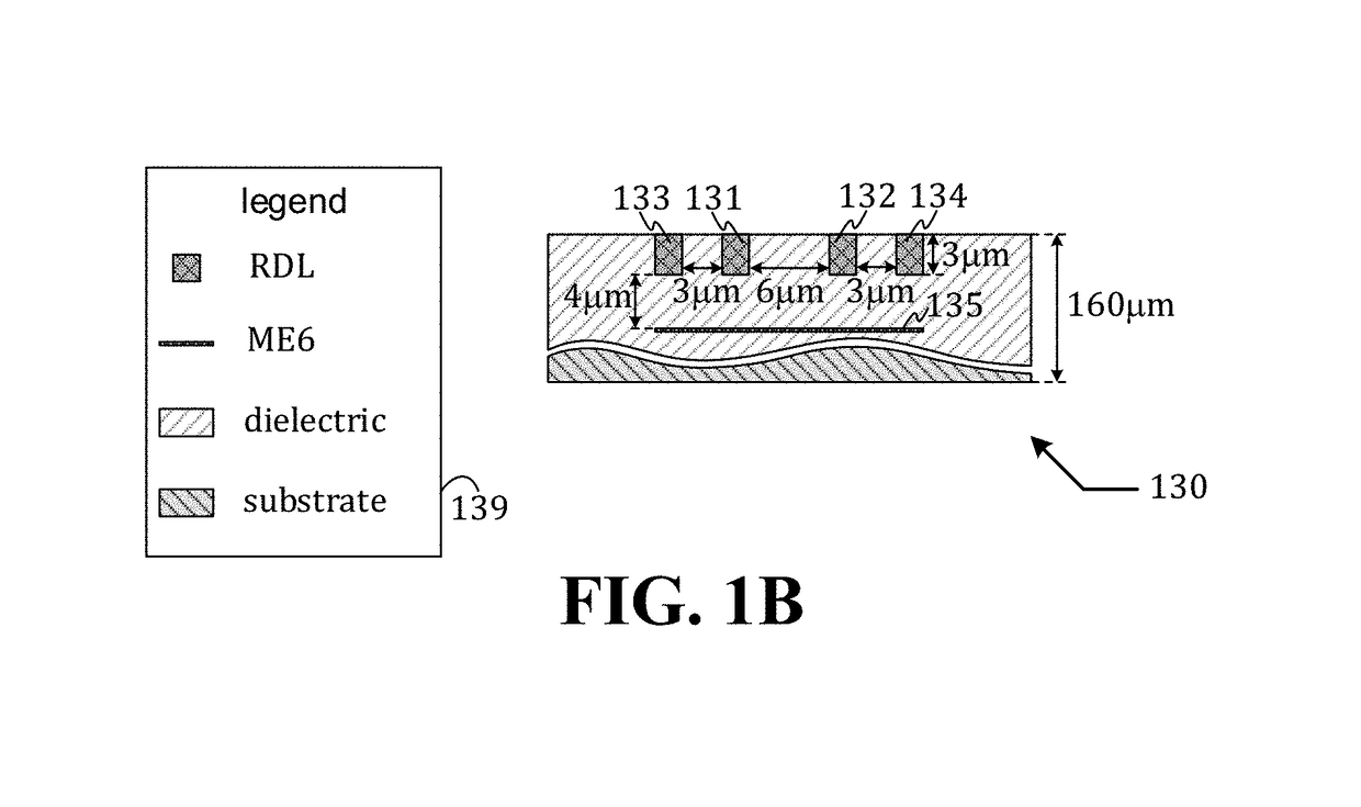
[0004]In an embodiment, a circuit comprises: a current source configured to output a bias current to a first node; a common-source differential amplifier pair configured to receive the bias current and output a first transmitted current and a second transmitted current to a second node and a third node, respectively, in accordance with a control of a differential input signal; a differential transmission line configured to receive the first transmitted current and the second transmitted current from the second node and the third node and output a first received current and a second received current to a fourth node and a fifth node, respectively; a current buffer configured to receive the first received current and the second received current from the fourth node and the fifth node and output a first output current and a second output current to a sixth node and a seventh node, respectively, wherein: the current buffer comprises: a common-gate amplifier pair, a first cross-coupling network configured to provide a negative feedback on the input side of the current buffer to reduce an input impedance of the current buffer, and a second cross-coupling network configured to provide a positive feedback on the output side of the current buffer to boost an output impedance of the current buffer; and a load configured to provide a termination at the sixth node and the seventh node to establish a first output voltage and a second output voltage, respectively.
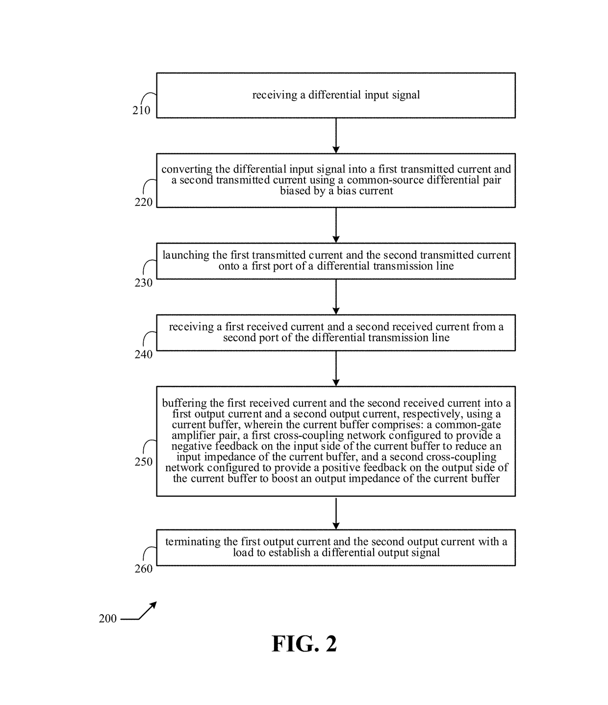
[0005]In an embodiment, a method comprises: receiving a differential input signal; converting the differential input signal into a first transmitted current and a second transmitted current using a common-source differential pair biased by a bias current; launching the first transmitted current and the second transmitted current onto a first port of a differential transmission line; receiving a first received current and a second received current from a second port of the differential transmission line; buffering the first received current and the second received current into a first output current and a second output current, respectively, using a current buffer, wherein the current buffer comprises: a common-gate amplifier pair, a first cross-coupling network configured to provide a negative feedback on the input side of the current buffer to reduce an input impedance of the current buffer, and a second cross-coupling network configured to provide a positive feedback on the output side of the current buffer to boost an output impedance of the current buffer; and terminating the first output current and the second output current with a load to establish a differential output signal.

Problems solved by technology

In a case where the clock generation circuit and a synchronous digital circuit that needs to receive the clock from the clock generation circuit are physically separated by a long distance (long in relation to the clock frequency), the transmission of the clock can be challenging.
The-long distance transmission of the clock usually suffers a large insertion loss, resulting in a weak signal on the receiving end.
The problem worsens when the clock is a high-speed clock, since the insertion loss of a transmission line increases as a frequency of the transmitted signal increases.

Method used


Image

  • Method and apparatus for high speed clock transmission
  • Method and apparatus for high speed clock transmission
  • Method and apparatus for high speed clock transmission

Examples


Embodiment Construction

[0009]The present disclosure is directed to clock transmission. While the specification describes several example embodiments of the disclosure considered favorable modes of practicing the invention, it should be understood that the invention can be implemented in many ways and is not limited to the particular examples described below or to the particular manner in which any features of such examples are implemented. In other instances, well-known details are not shown or described to avoid obscuring aspects of the disclosure.

[0010]Persons of ordinary skill in the art understand terms and basic concepts related to microelectronics that are used in this disclosure, such as “circuit node,”“power supply node,”“ground node,”“differential signal,”“differential-pair”“voltage,”“current,”“CMOS (complementary metal oxide semiconductor),”“PMOS (P-channel metal oxide semiconductor) transistor,”“NMOS (N-channel metal oxide semiconductor) transistor,”“resistor,”“inductor,”“capacitor,”“resonant t...


PUM


Abstract

A method comprises: receiving a differential input signal; converting the differential input signal into a first transmitted current and a second transmitted current using a common-source differential pair biased by a bias current; launching the first transmitted current and the second transmitted current onto a first port of a differential transmission line; receiving a first received current and a second received current from a second port of the differential transmission line; buffering the first received current and the second received current into a first output current and a second output current, respectively, using a current buffer, wherein the current buffer comprises: a common-gate amplifier pair, a first cross-coupling network configured to provide a negative feedback on the input side of the current buffer to reduce an input impedance of the current buffer, and a second cross-coupling network configured to provide a positive feedback on the output side of the current buffer to boost an output impedance of the current buffer; and terminating the first output current and the second output current with a load to establish a differential output signal.

Description

BACKGROUND OF THE DISCLOSUREField of the Disclosure[0001]The present disclosure generally relates to clock transmission, and more particularly high-speed clock transmission circuits.Description of Related Art[0002]As is known, a clock is a voltage signal that oscillates between a low level and a high level. Clocks are widely used in synchronous digital circuits for coordinating actions of the synchronous digital circuits. An integrated circuit that contains a plurality of synchronous digital circuits usually has a clock generation circuit, e.g. a phase lock loop, configured to generate a clock, which usually needs to be transmitted through a transmission line to the plurality of synchronous digital circuits to coordinate actions thereof. In a case where the clock generation circuit and a synchronous digital circuit that needs to receive the clock from the clock generation circuit are physically separated by a long distance (long in relation to the clock frequency), the transmission ...

Claims


Application Information

Patent Timeline
Patent Type & Authority Patents(United States)
IPC IPC(8): H03K3/023H03K3/011H03K3/356
CPCH03K3/023H03K3/356104H03K3/011H03K19/017509H03K19/017545G06F1/10H04L25/0272
Inventor LIN, CHIA-LIANG LEONSONG, FEI
Owner REALTEK SEMICON CORP
Why Eureka
Try Eureka