System and method for computer-assisted planning of a trajectory for a surgical insertion into a skull

a technology of surgical insertion and computer assisted planning, which is applied in the field of computer-aided planning/modelling, instruments, surgery, etc., can solve the problems of invasive investigation, affecting the surgical insertion process, so as to improve the planning of intracranial insertion, provide safer trajectories, and reduce the tim

Active Publication Date: 2019-03-12
UCL BUSINESS PLC
View PDF1 Cites 21 Cited by
  • Summary
  • Abstract
  • Description
  • Claims
  • Application Information

AI Technical Summary

Benefits of technology

[0008]Checking that the entry angle for an entry point is suitably perpendicular (otherwise it becomes much more difficult to drill the entry point through the skull) is computationally quicker than assessing the risk factor based on the separation between the critical objects and the trajectory which is associated with the entry point. Accordingly, a first set of entry points is initially filtered using the entry angle condition, which generally eliminates a majority of this first set of entry points to form a second set containing fewer entry points. The assessment of the risk factor based on separation then only has to be performed on the reduced number of entry points included in the second set, thereby helping with overall computational efficiency in order to provide a real-time and interactive system.
[0028]A significant application of this approach is in SEEG, which involves the placement of multiple depth electrodes into the brain to record seizure activity and precisely identify an area to be resected. Two important criteria for electrode implantation are accurate navigation to the target area, and avoidance of critical structures such as blood vessels. A typical SEEG implantation contains 8-12 electrodes, each placed to hit a unique target area. The arrangement of electrodes is planned so that each individual electrode meets specific criteria in terms of risk, as well as ensuring that electrodes are placed so as to prevent interference from the other electrodes. The computer-implemented approach described herein for computer-assisted planning facilitates the identification and selection of a good (hopefully optimum) electrode arrangement.

Problems solved by technology

A significant challenge in epilepsy surgery now is in the treatment of the more difficult patient groups (extratemporal non-lesional), where SEEG is increasingly utilised.
This invasive investigation carries the risks of infection, haemorrhage and neurological deficit [5].
In all of these approaches, the operator selects the target point precisely and the time required to compute the optimized paths is generally long.
Nevertheless, the pre-operative planning of electrode placement for stereo-electroencephalography and other such intra-cranial procedures is still frequently viewed as a relatively difficult and time-consuming process.

Method used


Image

  • System and method for computer-assisted planning of a trajectory for a surgical insertion into a skull
  • System and method for computer-assisted planning of a trajectory for a surgical insertion into a skull
  • System and method for computer-assisted planning of a trajectory for a surgical insertion into a skull

Examples


Embodiment Construction

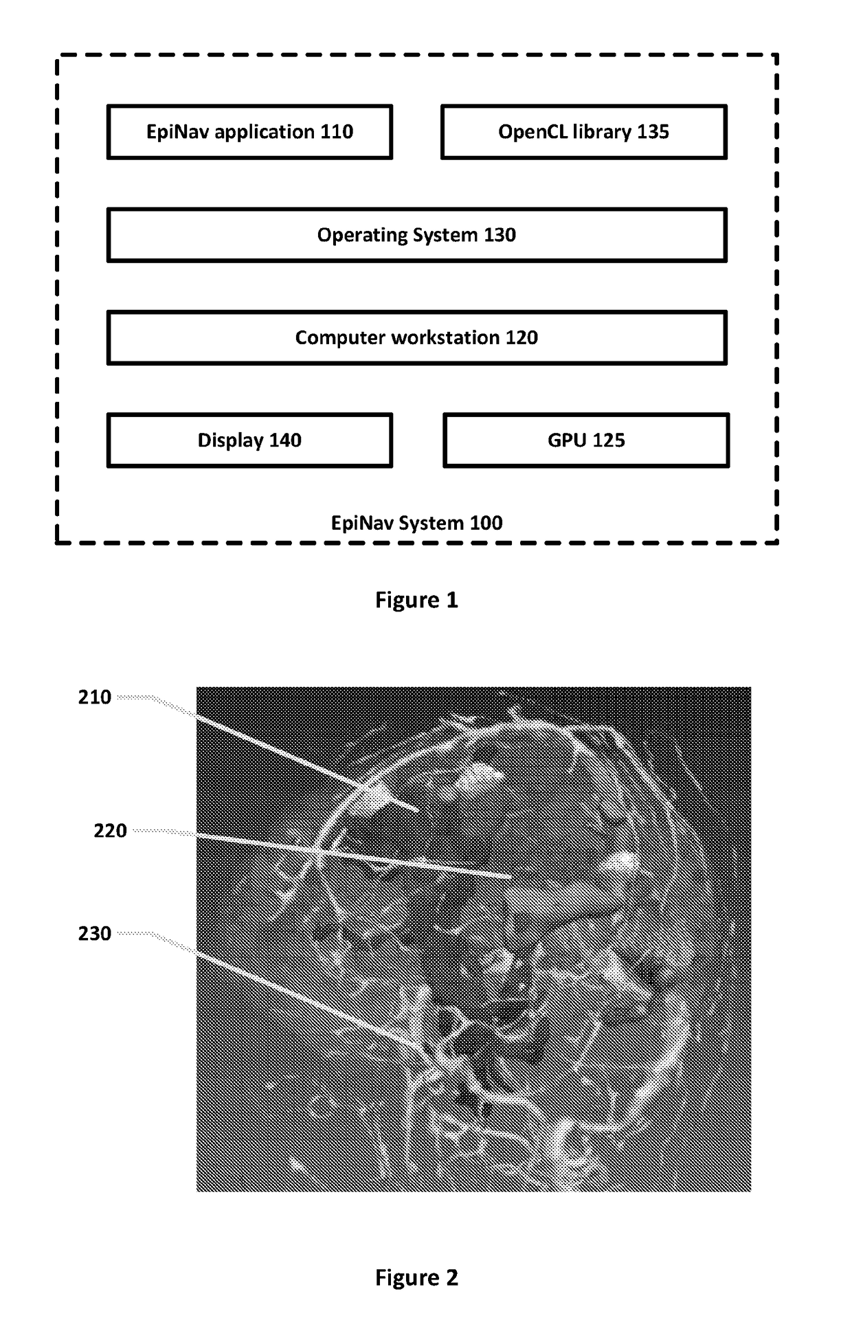
[0039]FIG. 1 is a schematic block of an interactive and responsive tool (the EpiNav™ system) 100 for the pre-operative planning of SEEG electrode placement in accordance with some embodiments of the invention. The main software application component 110 (the EpiNav application) was developed using a cross platform C++ library NifTK (www.niftk.org) that is based on the Medical Imaging and Interaction Toolkit (MITK, www.mitk.org) [14]. The software runs on a (modern) computer workstation such as a personal computer (PC) 120 which is provided with (at least one) display 140, and a (modern) graphics card (graphics processing unit, GPU) 125 which functions as general-purpose parallel processor. (The PC 120 will generally also be provided with standard accessories, such as a mouse, keyboard, etc, not explicitly shown in FIG. 1). The PC has an operating system 130, such as Mac OS X, Linux or Windows, and also has the OpenCL (Open computing language) library 135 from the Khronos Group insta...


PUM


Abstract

A system and method are provided for using a computer system to assist in planning a trajectory (960A, 960B) for a surgical insertion into a skull. The method comprises providing the computer system with a three-dimensional representation of the skull and of critical objects located within the skull, wherein the critical objects comprise anatomical features to be avoided during the surgical insertion. The method further comprises providing the computer system with a target location (770, 970) for the insertion within the skull. The method further comprises generating by the computer system a first set comprising a plurality of entry points, each entry point (760) representing a surface location on the skull, and each entry point (760) being associated (2D) with a trajectory (960A, 960B) from the entry point (760) to the target location (770, 970). The method further comprises discarding by the computer system entry points from the first set to form a second, reduced set comprising a plurality of entry points, wherein an entry point (760) is discarded from the first set of entry points if the entry point (760) has an entry angle which fails a condition for being substantially perpendicular to the skull surface. For each entry point (760) in the second set, the computer system assess the entry point (760) against a set of one or more criteria, wherein the set of one or more criteria includes a risk factor based on the separation between the critical objects and the trajectory (960A, 960B) which is associated with said entry point (760)). This risk factor may be calculated by integrating f(x) along the trajectory (960A, 960B) associated (2D) with the entry point (760), where x represents distance along the trajectory (960A, 960B) to a sample point, and f(x) is a function based on distance from the sample point at distance x to a critical object which is nearest to said sample point.

Description

FIELD OF THE INVENTION[0001]The present invention relates to a system and method for computer-assisted planning of a trajectory for a surgical insertion into a skull (intra-cranial insertion), such as for the pre-operative planning of electrode placement for stereo-electroencephalography.BACKGROUND OF THE INVENTION[0002]Approximately 20-30% of patients with focal epilepsy are medically refractory to treatment with anti-epileptic drugs. These patients are potential candidates for curative respective surgery [1, 2]. The primary aim of epilepsy surgery is to remove the epileptogenic zone: “the minimum amount of cortex that must be resected (inactivated or completely disconnected) to produce seizure freedom” [3, 4]. The identification of the epileptogenic zone usually involves the placement of intracranial electrodes to record where seizures start and rapidly propagate. Stereo-electroencephalography (SEEG) is the practice of recording electroencephalographic signals via depth electrodes...

Claims


Application Information

Patent Timeline
Patent Type & Authority Patents(United States)
IPC IPC(8): A61B34/10G06F17/50
CPCA61B34/10G06F17/50A61B2034/107A61B2034/105G06F30/00
Inventor OURSELIN, SEBASTIENZOMBORI, GERGELYNOWELL, MARKSPARKS, RACHELDUNCAN, JOHNRODIONOV, ROMANMCEVOY, ANDREWMISEROCCHI, ANNADIEHL, BEATEWEHNER, TIM
Owner UCL BUSINESS PLC
Why Eureka
Try Eureka