Electroplating apparatus with electrolyte agitation

a technology of electroplating apparatus and liquid electrolyte, which is applied in the direction of electrolysis components, contact devices, tanks, etc., can solve the problems of reducing the mass transfer rate of electrolyte components, reducing the quality and efficiency of plating process, and less effective shields, etc., to achieve improved mass transfer, large gap, and larger vortices

Active Publication Date: 2019-03-12
APPLIED MATERIALS INC
View PDF17 Cites 4 Cited by
  • Summary
  • Abstract
  • Description
  • Claims
  • Application Information

AI Technical Summary

Benefits of technology

[0005]Experimental and computation results disclose a relationship between the dimension of the gap between the paddle and the wafer, and the vortex size for achieving improved mass transfer. Specifically, the inventors have discovered that in processor designs having a larger gap, using a paddle which creates larger vortices provides improved results. Consequently, in designs having a shield is at a vertical position above the paddle, making the gap larger, a paddle having ribs spaced farther apart provides better mass transfer by creating larger vortices. The vortices may also be made more consistently across the wafer providing more uniform mass-transfer.
[0006]In one aspect, an electroplating apparatus agitates electrolyte to provide high velocity fluid flow at the surface of a wafer that results in results in high, uniform mass transfer providing more uniform plating at high plating rates. The apparatus includes a paddle which can provide uniform high mass transfer over the entire wafer, even with a relatively large gap between the paddle and the wafer. Consequently, the processor may have an electric field shield positioned between the paddle and the wafer, where the shield is more effective. In this design, with the paddle below the shield, the paddle is also less likely to adversely influence the electric field across the wafer. This advantage is particularly significant in processing where the wafer does not rotate, where such disturbances cannot be averaged out with wafer rotation.

Problems solved by technology

The diffusion layer reduces the mass transfer rate of electrolyte components and reactants to the surface of the wafer, which degrades the quality and efficiency of the plating process.
If the shield is positioned below the paddle, the shield is less effective.
If the shield is positioned above the paddle, then the paddle is less effective, as the gap between the paddle and the wafer is larger.
Accordingly, engineering challenges remain in designing electro-plating apparatus.

Method used


Image

  • Electroplating apparatus with electrolyte agitation
  • Electroplating apparatus with electrolyte agitation
  • Electroplating apparatus with electrolyte agitation

Examples


Embodiment Construction

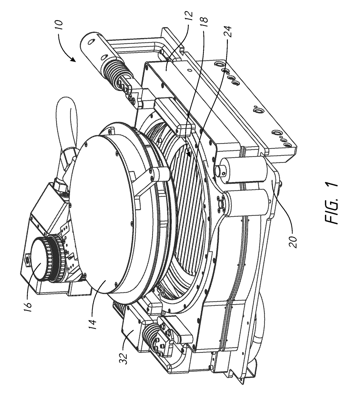
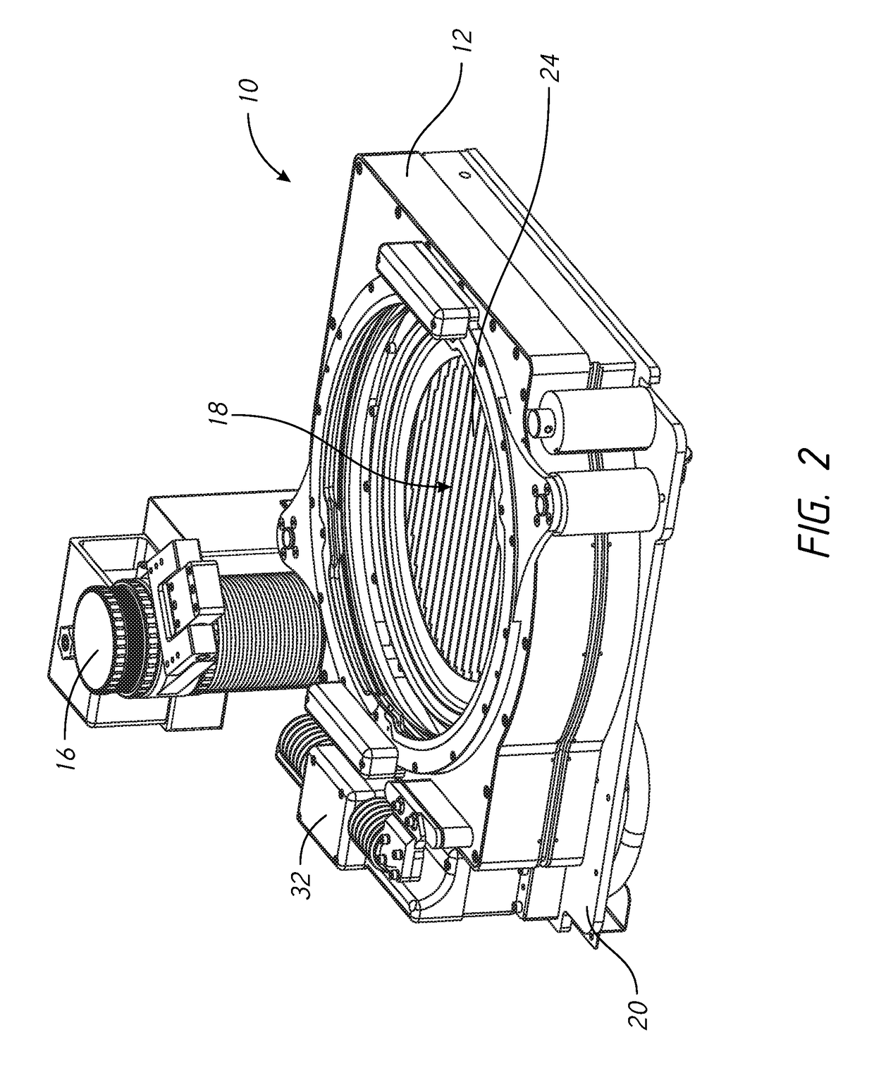
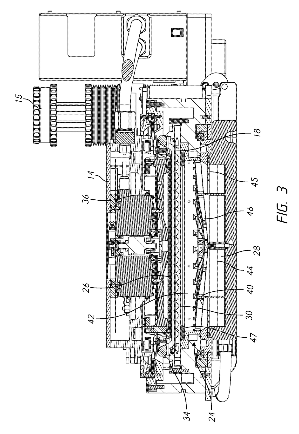
[0014]As shown in FIGS. 1-3, a processor 10 for electroplating a wafer 30 includes a head 14 supported on a head lifter 16 and a vessel 24. A membrane 40 may be included to divide the vessel 24 into a lower chamber 44 containing one or more anodes 28, and a first liquid electrolyte, below the membrane 40, and an upper chamber 42 containing a second liquid electrolyte. Alternatively the membrane 40 may be omitted with the vessel 24 having a single chamber holding a single electrolyte. Referring to FIG. 3, a field shaping element 46 made of a dielectric material may be provided in the vessel 24 primarily to support the membrane 40, and distribute flow of catholyte. The electric field in the vessel 24 may be shaped via an anode shield 45, a chamber shield 47, and a weir shield 34. The shields may be annular dielectric elements. The shields provide shielding of the electric field with the vessel.

[0015]A contact ring 26 on the head 14 holds the wafer 30 and has a plurality of contact fin...


PUM

PropertyMeasurementUnit
height HHaaaaaaaaaa
height HHaaaaaaaaaa
thicknessaaaaaaaaaa

Abstract

Electroplating apparatus agitates electrolyte to provide high velocity fluid flows at the surface of a wafer. The apparatus includes a paddle which provides uniform high mass transfer over the entire wafer, even with a relatively large gap between the paddle and the wafer. Consequently, the processor may have an electric field shield positioned between the paddle and the wafer for effective shielding at the edges of the wafer. The influence of the paddle on the electric field across the wafer is reduced as the paddle is spaced relatively farther from the wafer.

Description

TECHNICAL FIELD[0001]The field of the invention is apparatus and methods for agitating liquid electrolyte in an electroplating apparatus.BACKGROUND OF THE INVENTION[0002]In many plating processes, a diffusion layer forms in the liquid electrolyte at the surface of the wafer. The diffusion layer reduces the mass transfer rate of electrolyte components and reactants to the surface of the wafer, which degrades the quality and efficiency of the plating process. One technique for increasing the mass transfer rate is to increase the relative velocity between the liquid electrolyte and the surface of the workpiece. In the past, some processing apparatus have used a paddle which oscillates horizontally or vertically in the electrolyte. The paddle has spaced apart ribs or blades. As the paddle moves, a liquid vortex is formed in the spaces between adjacent ribs. The liquid vortex creates a high speed agitated flow at or against the lower (down-facing) surface of the workpiece, increasing the...

Claims


Application Information

Patent Timeline
Patent Type & Authority Patents(United States)
IPC IPC(8): C25B9/00C25D17/00C25D21/10C25D5/08
CPCC25D17/001C25D21/10C25D5/08C25D7/12C25D17/00C25D17/005C25D17/08C25D17/02C25D17/06C25D17/10
Inventor WILSON, GREGORY J.MCHUGH, PAUL R.
Owner APPLIED MATERIALS INC
Why Eureka
Try Eureka