Wound contacting members and methods

a technology for contacting members and wounds, applied in the field of wound contacting members and methods, can solve the problems of requiring rapid growth of (tissues), affecting the healing effect,

Active Publication Date: 2019-04-02
SMITH & NEPHEW PLC
View PDF329 Cites 8 Cited by
  • Summary
  • Abstract
  • Description
  • Claims
  • Application Information

AI Technical Summary

Benefits of technology

[0011]It is an aim of embodiments of the present invention to provide improved wound contacting materials compared to known materials.
[0012]It is an aim of embodiments of the present invention to provide apparatus and methods for preventing, minimizing, delaying, reducing or inhibiting tissue in-growth.
[0013]It is an aim of embodiments of the present invention to provide a wound filler or wound contacting member that reduces in-growth whilst also promoting the formation of granulation tissue.
[0068]Certain embodiments provide the advantage that in-growth of tissue to a wound contacting member or filler within a conventional time period (such as 3 days) is completely or substantially prevented. Removal of a wound contacting member from the wound site is therefore less painful for the patient, and less damaging to the tissue at the wound site compared to known materials. Certain embodiments provide the advantage that an advantageous degree of granulation tissue is stimulated by the presence of the wound contacting member. This enables a faster healing process to be accomplished at the wound compared to known methods and apparatus. Certain embodiments provide an improved wound treatment apparatus and method for NPWT (for example at pressure of between 40 and 200 mmHg below atmospheric).

Problems solved by technology

The wounds may also have significant depth and therefore significant volume.
In particular, large wounds where considerable tissue loss has been experienced by the patient often require rapid growth of (tissue before closure can take place.
When negative pressure is applied to a wound site, there is a tendency for the filler to collapse and be pushed towards the wound bed.
Both these types of filler allow good transmission of negative pressure and allow fluid removal, yet suffer from various drawbacks.
Foam fillers often suffer from the fact that tissue can grow into the foam structure.
The foam may become stuck to the wound bed, making the filler difficult to remove when changing the dressing.
Newly formed granulation tissue may be torn away with the foam when the filler is removed, which may cause patient pain during removal of the filler.
This can be traumatic to the wound and to the patient.
The clinician is often faced with having to compromise between changing a dressing early to keep tissue in-growth to a minimum and leaving the dressing in place to minimize nursing time, treatment cost and patient access.
This is a particular problem with current open pore foam fillers (i.e. foam having a very open pore structure).
Thus use of open pore wound fillers tends to be limited to 2 to 3 days, beyond which significant tissue in-growth and subsequent attachment is thought to occur, at least potentially resulting in damage to the tissue and pain on removal.
Gauze fillers and mixed open-cell / closed-cell foam fillers (e.g. poly vinyl alcohol based foam) generally perform better with respect to in-growth, but may be inferior in their ability to induce comparable levels of observed granulation tissue.
It is well known that the inclusion of a wound contact layer located between the filler and the wound surface reduces the chance of tissue growing into the foam, although again this is to the detriment of reducing the observed granulation tissue formation.
However, this has always been at the expense of limiting granulation tissue growth and thus overall clinical efficacy.

Method used


Image

  • Wound contacting members and methods
  • Wound contacting members and methods
  • Wound contacting members and methods

Examples


example 1

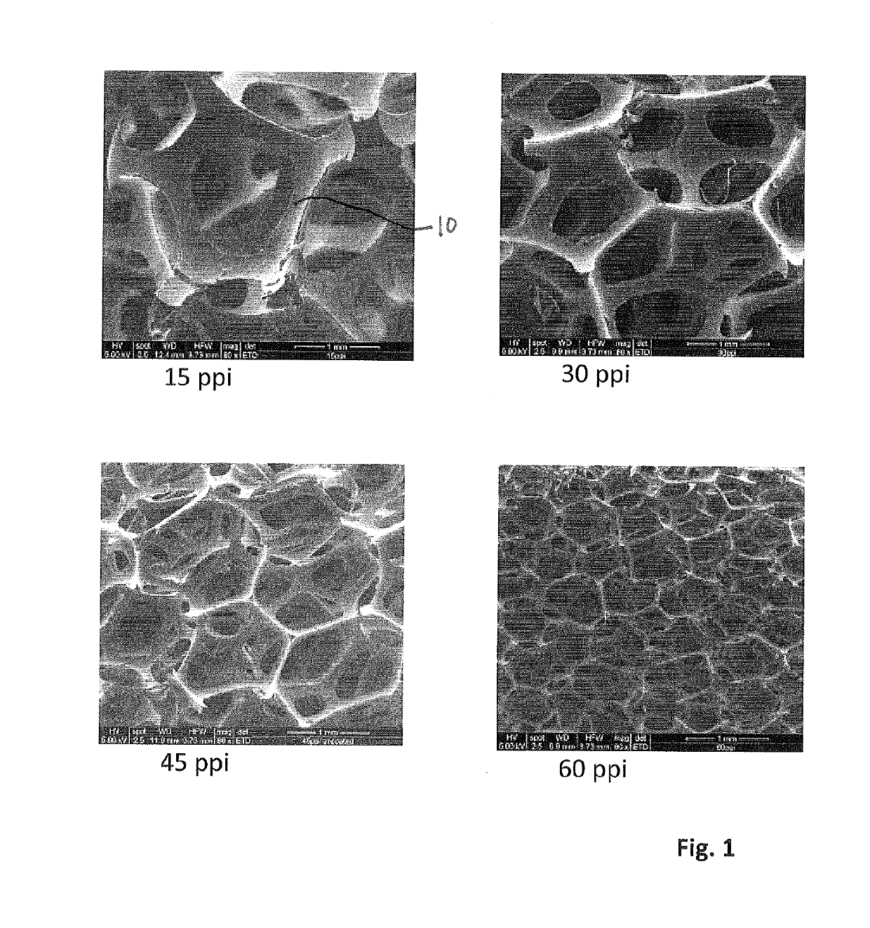
[0134]The inventors tested parameters of a number of foams having different pore counts including 15 ppi, 30 ppi, 45 ppi and 60 ppi foam. Results are shown in Table 1, below.

[0135]The inventors viewed the foams under stereomicroscope and scanning electron microscope (SEM). Images from the SEM study are shown in FIG. 1. The inventors also viewed the foams in a compressed state under SEM.

[0136]The inventors calculated foam density and foam ‘openness’ including the percentage of struts, surface area of the struts, percentage of pores, and anisotropy of the pore space, using the techniques described below under ‘Measurement Techniques’. Specifically, all measurements other than average density were measured by micro-CT analysis as described below.

[0137]

TABLE 1Parameter15 ppi30 ppi45 ppi60 ppiAverage density0.0310.0360.0280.027(g · cm−3)% strut presence2.83.52.22.3Surface area of92203202336the struts (mm2in a 126 mm3volume)% pores97.296.597.897.7Anisotropy of1.201.321.241.24pore spaceStr...

example 2

[0140]The inventors studied the effects of foams with different pore sizes under NPWT in an in-vivo porcine wound model. Wounds were created, a piece of foam was sutured to the wound for histological purposes, a further circular piece of foam of 6 cm diameter and 2 mm deep was added to the wound for pull-out force data purposes, and then the wound was treated with NPWT. Each wound was circular (i.e. having a circular wound base), 6 cm in diameter and 2 cm deep, reaching subcutaneous tissue.

[0141]After 72 hours NPWT at −125 mmHg constant pressure, the foam and underlying wound bed were cut away and inspected histologically using light microscopy. Images of the results are shown in FIG. 6. As can be seen from FIG. 6, the indentation of the strut 115 of the 15 ppi foam into the tissue of the wound bed 102 is significantly greater than the indentation of the strut 130 of the 30 ppi foam.

[0142]The average depth of imprint of the foam into the wound bed was also measured histologically. T...

example 3

[0152]The inventors tested parameters of a number of foam pieces having different pore counts including 10 ppi, 15 ppi, 20 ppi and 30 ppi. The results are shown in Table 3. The results shown in Table 3 relate to uncompressed (at rest) foam samples, unless labelled as ‘under compression’. For the ‘under compression’ data, samples of 40 mm×18 mm×30 mm (thickness of 30 mm) were compressed by sandwiching between two plastic slides and taping together, such that the sample had a thickness of 6 mm.

[0153]

TABLE 3Parameter10 ppi15 ppi20 ppi30 ppiNominal pore10152030count (ppi)Pore size as2.541.691.270.85calculatedfrom ppi (mm)Pore size0.25-1.620.25-1.420.22-1.320.15-0.89range -undercompression,as measuredby micro-CT(mm)Most frequent1.250.870.660.50pore size -undercompression,as measuredby micro-CT(mm)Pore size3.13-5.492.72-4.162.31-3.751.08-2.21range -notcompressed,as measuredby micro-CT(mm)Most frequent4.703.403.301.85pore size -notcompressed,as measuredby micro-CT(mm)Strut width0.007-0.631...


PUM


Abstract

Wound contacting members and methods, apparatuses, systems and kits incorporating the same are disclosed. The wound contacting members offer improved performance in terms of preventing or inhibiting tissue in-growth and improving tissue granulation growth. The wound contacting members may be used in negative pressure wound therapy (NPWT) applications.

Description

CROSS-REFERENCE TO RELATED APPLICATIONS[0001]This application is a U.S. National Phase of the PCT International Application No. PCT / GB2012 / 000489, filed on Jun. 7, 2012, and which claims priority to UK Application Nos. 1109497.6, 1109500.7, and 1109502.3, all filed on Jun. 7, 2011.FIELD OF THE INVENTION[0002]Embodiments of the present invention relate to wound contacting members and methods, apparatuses, systems and kits incorporating the same. In particular, but not exclusively, embodiments relate to foam for preventing or inhibiting tissue in-growth and / or improving tissue granulation growth, a wound filler configured to prevent or inhibit tissue in-growth and / or improve tissue granulation growth, a method of treating a wound to prevent or inhibit tissue in-growth and / or improve tissue granulation growth, and apparatus for treating a wound. The wound contacting members of the some embodiments may be used in negative pressure wound therapy (NPWT) applications. Certain embodiments r...

Claims


Application Information

Patent Timeline
Patent Type & Authority Patents(United States)
IPC IPC(8): A61M1/00A61F13/00
CPCA61F13/00068A61M1/0088A61F2013/00174A61F2013/0028A61M1/915A61M1/916A61F13/00A61F13/0216A61M27/00
Inventor HICKS, JOHN KENNETHHUDDLESTON, ELIZABETH MARY
Owner SMITH & NEPHEW PLC
Why Eureka
Try Eureka