Microbubble signal based temporal-bone thickness compensation for sonothrombolysis

a temporal bone thickness compensation and microbubble signal technology, applied in the field of quantifying the ultrasound dose of sonothrombolysis, can solve the problems of degrading the ability to image the brain, low treatment success, and significant restrictions on their use, and achieve the effect of wide deployment and simplified implementation

Inactive Publication Date: 2019-04-16
KONINKLJIJKE PHILIPS NV
View PDF8 Cites 0 Cited by
  • Summary
  • Abstract
  • Description
  • Claims
  • Application Information

AI Technical Summary

Benefits of technology

[0007]Proposed herein below are a novel non-invasive method, device, and software to compensate the ultrasound amplitude (i.e. by either increasing or decreasing it), so that the clot is always being insonified by the correct ultrasound pressure to achieve reliable clot dissolution and vessel recanalization, regardless of the attenuation characteristics of the patient's temporal bone. This technological solution exploits a characteristic behavior of microbubbles and their ultrasonic imaging signature when subjected to varying pressure ultrasound pulses. This behavior, which the instant inventors discovered, is, as described further below, virtually independent of microbubble concentration (in circulation), as well as blood circulation speed, thus requiring no a priori knowledge of the brain's perfusion characteristics and patient anatomy, nor requiring any other type of specific calibration. This makes compensating for the temporal bone thickness possible in a simple, non-patient-specific way that does not require calibration, and is independent of the patient-specific physiology. This simplifies implementation and allows for wide deployment.
[0008]The temporal bone compensation can be accomplished by a single ultrasound transducer, thus simplifying the overall STL device design, and potentially allowing implementation on existing ultrasound systems / scanners.
[0010]The technique eliminates the need for any patient-specific a priori information, and does not require patient-specific calibration, both of these factors simplifying implementation and allowing wide deployment.

Problems solved by technology

One of the advantages of STL treatments is that they can be performed without the use of drugs (such as t-PA, or tissue plasminogen activator, a common “clotbusting” drug), which carry with them significant restrictions to their use, and overall low treatment success.
One challenge associated with STL treatments is that the ultrasound energy is delivered to the clot location inside the patient's brain through the skull.
Even so, the temporal bone attenuates ultrasound significantly, degrading the ability to image the brain, and also making it more difficult to deliver the required ultrasound energies for successful STL treatments.
Another challenge associated with STL treatments is that the thickness and consequent attenuation of the temporal bone vary from patient to patient, potentially resulting in either higher or lower ultrasound energies being delivered to the clot location, with the potential of causing undesired bioeffects (in the case of a thinner temporal bone yielding higher ultrasound pressures in the brain), or not being able to dissolve the clot at all (in the case of a thicker temporal bone yielding lower ultrasound pressures in the brain).

Method used


Image

  • Microbubble signal based temporal-bone thickness compensation for sonothrombolysis
  • Microbubble signal based temporal-bone thickness compensation for sonothrombolysis
  • Microbubble signal based temporal-bone thickness compensation for sonothrombolysis

Examples


Embodiment Construction

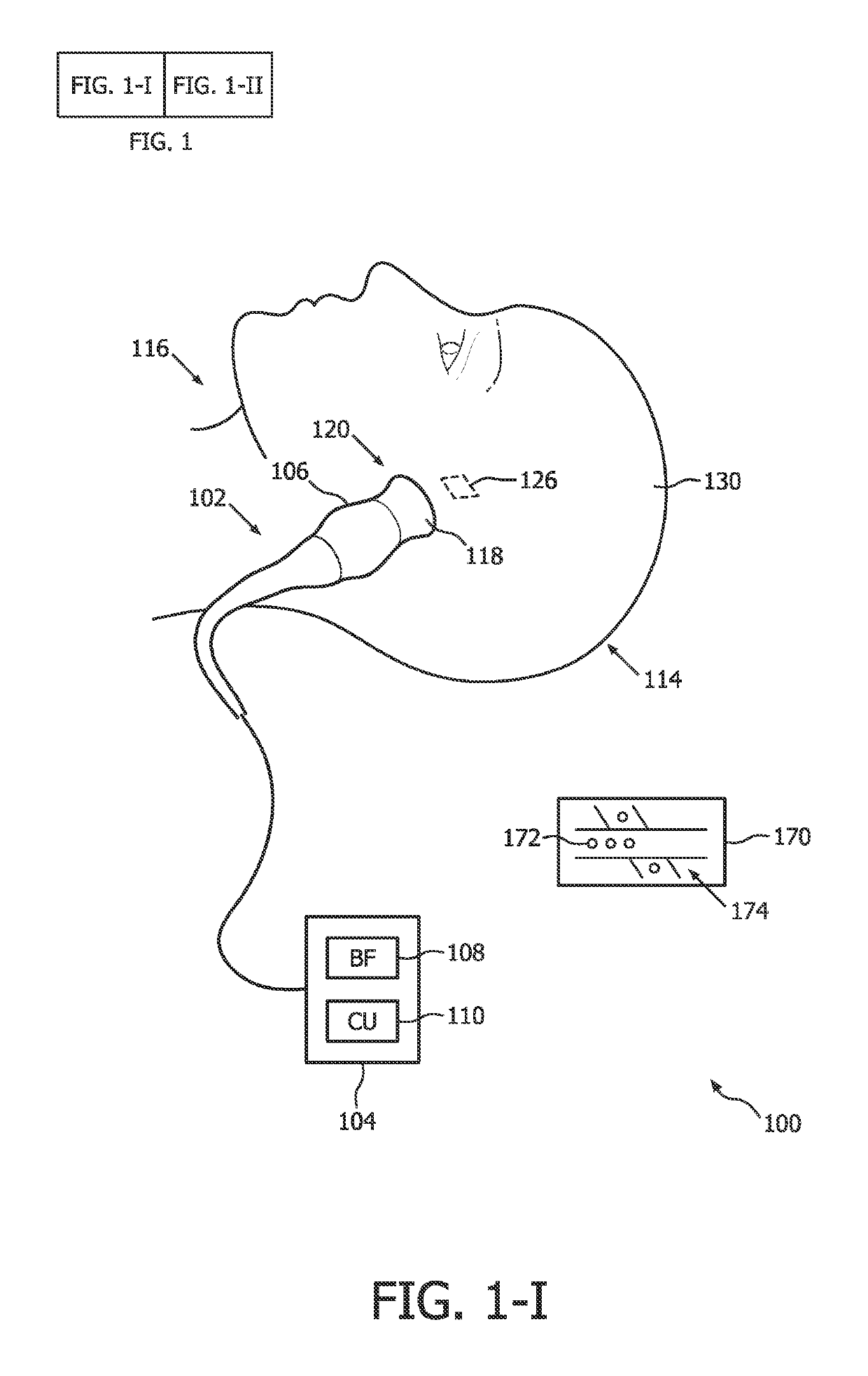
[0021]An ultrasound-based intracranial sonothrombolysis (STL) treatment and ultrasound-dose pre-quantification apparatus 100 is depicted by way of illustrative and non-limitative example in FIG. 1.

[0022]The apparatus 100 includes an ultrasound scanner 102 which further includes a console 104 and an imaging and therapy ultrasound probe 106. The console 104 includes a transmit and receive beamformer 108, and an ultrasound-scanner control unit 110. The console 104 will typically include other components, such as interactive user controls and a display, both of which are not shown. Incorporated within the console 104 is control logic, such as one or more integrated circuits and in any combination of software, hardware, and firmware.

[0023]The apparatus further comprises a head frame, head cap, headband, or headset, (not shown) for securing the probe 106 against a head 114 of a medical treatment recipient 116, such as a patient diagnosed with acute ischemic stroke. Such headpieces for int...


PUM


Abstract

An ultrasonic intracranial sonothrombolysis pressure amplitude is pre-quantified by using an ultrasound-scanner control unit (110) having an increasing and / or decreasing mode and designed for: with respect to a current mode, interrogating a blockage site iteratively so as to progressively and respectively increase or decrease a pressure amplitude of ultrasound being emitted to the site at which bubbles (144) for oscillating that is caused by the emitted ultrasound are present; iteration to iteration, deriving, from echoes of the emitted ultrasound, a magnitude of an energy of a signal; and automatically identifying, for the quantifying, an iteration that, in comparison with a just-previous iteration, fails to increase the magnitude. The interrogating may span a region that contains or goes through: the obstruction; another part of the blood vessel; and bubble circulation within a neighboring vessel and a neighboring capillary (136). The deriving can be based on an ultraharmonic signal, with band-pass filtering being utilized to extract the ultraharmonic signal from returning signals differenced to remove stationary content.

Description

[0001]This application is the U.S. National Phase application under 35 U.S.C. § 371 of International Application No. PCT / IB2015 / 059229, filed on Dec. 1, 2015, which claims the benefit of U.S. Provisional Application Ser. No. 62 / 090,701, filed Dec. 11, 2014. These applications are hereby incorporated by reference herein.FIELD OF THE INVENTION[0002]The present invention relates to quantifying an ultrasound dose for sonothrombolysis and, more particularly, to such quantifying based on a preparatory stage of ultrasound feedback.BACKGROUND OF THE INVENTION[0003]Sonothrombolysis (STL) treatments for acute stroke rely on ultrasound energy (targeting the clot) delivered through the temporal bone and microbubbles injected systemically to achieve clot dissolution and vessel recanalization.[0004]Sonothrombolysis treatments are being investigated by a multitude of researchers and clinicians for their potential role in treating acute stroke. In STL treatments, ultrasound pulses are delivered thr...

Claims


Application Information

Patent Timeline
Patent Type & Authority Patents(United States)
IPC IPC(8): A61B8/08A61B8/00A61B17/22A61N7/00A61B17/225
CPCA61B8/0808A61B8/54A61B17/22004A61N7/00A61B8/085A61B8/481A61B8/587A61B2017/22008A61N2007/0039A61N2007/0052A61B17/2256
Inventor SEIP, RALFSHI, WILLIAM TAO
Owner KONINKLJIJKE PHILIPS NV
Why Eureka
Try Eureka